800-543-9038 USA 866-805-7089 CANADA 203-791-8396 LATIN AMERICA / CARIBBEAN
Torque min. 180 in-lb, for control of air dampers
A
licatio
For proportional modulation of dampers in HVAC systems. Actuator sizing should be
done in accordance with the damper manufacturer’s specifications
The actuator is mounted directly to a damper sha
t up to 1.05” in diameter by means
f its universal clamp. A crank arm and several mountin
brackets are available for
pplications where the actuator cannot be direct coupled to the damper shaft
The actuator operates in response to a 2 to 10 VDC, or with the addition of a 50
esistor, a 4 to 20 mA control in
ut from an electronic controller or
ositioner. A 2 to
10 VDC feedback signal is provided for position indication. Not to be used for a
master-slave a
lication
O
eratio
The AFB N4
H
, AFX N4 series actuators provide true sprin
return operation for
eliable fail-safe application and positive close-off on air ti
ht dampers. The sprin
eturn s
stem
rovides constant tor
ue to the dam
er with, and without,
ower
e
to t
e actuator
The AFB N4(H), AFX N4 series provides 95° of rotation and is provided with a
gra
uate
pos
t
on
n
cator s
ow
ng 0° to 95°.
The AFB24-SR N4(H), AFX24-SR N4 uses a brushless DC motor which is controlled by
n Application Specific Integrated Circuit (ASIC) and a microprocessor. The
microprocessor provides the intelli
ence to the A
I
to provide a constant rotation rate
nd to know the actuator’s exact fail-safe position. The A
I
monitors and controls the
rushless D
motor’s rotation and provides a digital rotation sensing function to
revent
amage to t
e actuator
n a sta
con
t
on.
e actuator may
e sta
e
nywhere in its normal rotation without the need o
mechanical end switches.
The AFB24-SR-S N4
H
, AFX24-SR-S N4 version are provided with two built-in
uxiliary switches. These SPDT switches provide safety interfacing or signaling, for
example,
or
an start-up. The switching
unction at the
ail-sa
e position is
ixed at
+10°, the other switch
unction is adjustable between +10° to +90°
TTENTI
N: AFB24-SR(-S) N4(H) and AFX24-SR(-S) N4
ann
be tandem
mounted on the same dam
er or valve shaft. Onl
On/Off and MFT AF models can
e used
or tandem mount a
lications.
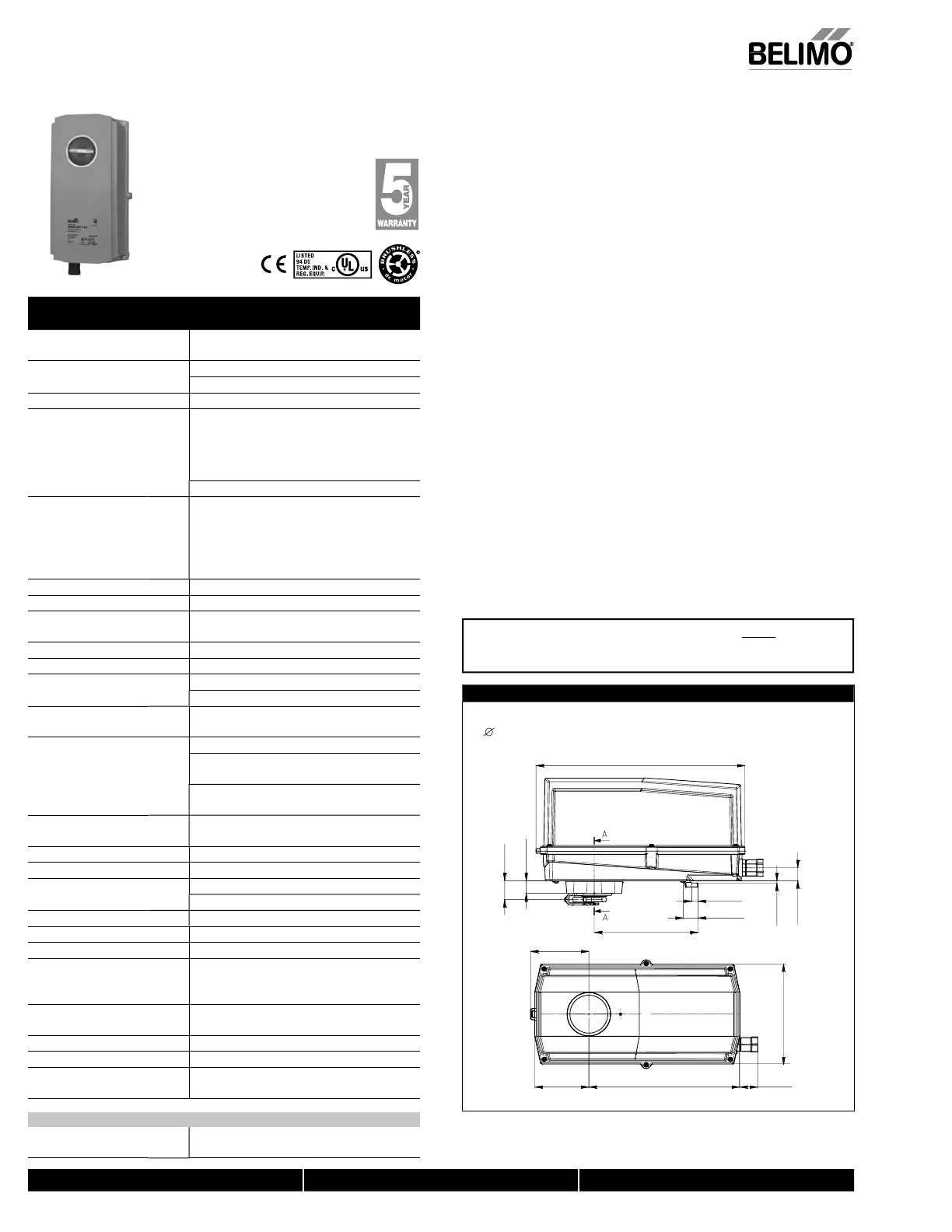
Dimensions (inches [mm])
6.77” [172]
Clamp Congurations
1/2” Field Selectable 3/4” Centered 1.05” Centered
(Default) (Field Selectable)
12.99” [330]
6.45” [163.9]
0.39” [10]
0.92” [23.4]
3.62” [92.1]
9.37” [238] 1.12” [28.5]
3.36” [85.2]
3.5” [0.14]
0.81” [20.5]
1.17” [29.8]
0.79” [20]
312_Confi
Technical Data AFB24-SR N4(H) AFB24-SR-S N4(H),
AFX24-SR N4 AFX24-SR-S N4
Power su
l
24 VAC ±20%
50/60 H
24 VD
+20%
-10%
ower consumpt
on runn
ng
.
W
h
t
r 2
o
n
3
Trans
ormer sizing 6 VA (class 2 power source) / heater 25 V
Electrical connectio
AFB... N4 3 ft, 18
A appliance cable, 1
2" conduit
connecto
-
models: two 3
t, 18 gauge appliance cables
with 1/2” conduit connector
eater
N4H
terminal block
26-16 GA
ft
1m
, 10 ft
3m
or 16 ft
5m
18 GA
appliance or plenum cables, with 1/2” conduit
connecto
-S m
dels: Two 3
t
1m
, 10
t
3m
or
16 ft
5m
appliance cables with 1/2" conduit
connec
ors
verload
rotectio
electronic throu
hout 0 to 95° rotation
peratin
ran
e Y 2 to 10 VD
, 4 to 20m
Input impedanc
100 k
for 2 to 10 VD
(0.1 mA
500
or 4 to 20 mA
Feedback output U 2 to 10 VDC
max. 0.5 mA
Torque 180 in-lb
10 Nm
minimu
Direction of rotatio
sprin
reversible with CW/CCW mountin
Inside housin
oto
revers
e w
t
u
t-
n sw
tc
echanical angle o
rotatio
95°
a
usta
e w
t
mec
an
ca
en
stop, 35° to
95°
unn
ng t
me
m
t
r
95 secon
s
spr
n
< 20 seconds
-4°F to 122°F [-20°
to 50°
]
< 60 seconds @ -22°F
-30°C
sprin
with heater
< 20 seconds
-4°F to 122°F
-20°
to 50°
< 60 seconds
-49°F
-45°
P
iti
n in
i
ti
visual indicator, 0° to 95
0° is full sprin
return position
n
l
v
rri
5 mm hex crank
₁₆
Allen
, supplie
Humidit
max. 95% RH non-condensin
Ambient tem
eratur
-22°F to 122°F
-30°
to 50°
with heate
-49°F to 122°F [-45°
to 50°
torage temperature -40°F to 176°F [-40°
to 80°
Housin
UL Type 4, NEMA 4, IP6
ous
n
mater
a
po
ycar
onate
A
ency listin
cULus acc. to UL60730-1A
-2-14
AN
A
E60730-1:02
CE acc. to 2004/108/EC &
2
E
N
i
l
v
l ≤40dB(A) motor @ 95 second
62dB(A) spring return
ervicing m
int
n
n
fr
ualit
standar
I
9001
Weigh
9.7 lbs (4 kg); 10 lbs (4.5 kg) with switche
10.5 lbs (4.8 kg
† Rated Impulse Voltage 800V, Type of action 1.AA (1.AA.B for -
version),
ontrol Pollution Degree 4.
FB24-
R-
N4(H), AFB24-
R-
N4
Auxiliary switches 2 x
PDT 3A (0.5A)
250 VA
, UL approve
one set at +10°, one a
usta
e 10° to 90
AFB24-SR N4(H), AFB24-SR-S N4(H), AFX24-SR N4, AFX24-SR-S N
EMA 4, Proportional, Sprin
Return, 24 V, for 2 to 10 VDC or 4 to 20 mA Control Si
na
N40103 - 09/11 - Subject to change. © Belimo Aircontrols (USA), Inc
 Loading...


