800-543-9038 USA 866-805-7089 CANADA 203-791-8396 LATIN AMERICA / CARIBBEAN
Accessories
l-
mm
n
1
mm wr
n
3442-00001 Gland (needed for additional wires
1
7-
1 Gasket for Gland (needed for additional wires
NOTE
When using AFB24-SR N4(H), AFB24-SR-S N4(H), AFX24-SR N4, AFX24-SR-S N4 actuators,
nly use accessories listed on this pa
e.
For actuator wiring information and diagrams, refer to Belimo Wiring Guide
Typical Specification
pring return control damper actuators shall be direct coupled type which require no
rank arm and linkage and be capable of direct mounting to a jackshaft up to a 1.05”
diameter. The actuator must provide proportional damper control in response to a 2 to
10 VD
or
with the addition of a 50
Ω resistor, a 4 to 20 mA control in
ut from an
ectron
c contro
er or pos
t
oner.
e actuators must
e
es
gne
so t
at t
ey may
e
sed for either clockwise or counterclockwise fail-safe o
eration. Actuators shall use
a brushless DC motor controlled by a microprocessor and be protected from overload
at all angles of rotation. Run time shall be constant, and independent of torque. A 2 to
10 VDC feedback si
nal shall be provided for position feedback. Actuators shall be
ULus Approved and have a 5 year warranty, and be manufactured under ISO 9001
International Quality Control Standards. Actuators shall be as manufactured by Belimo.
AFB24-
R N4
H
, AFB24-
R-
N4
H
, AFX24-
R N4, AFX24-
R-
N4
NEMA 4, Proportional, Sprin
Return, 24 V, for 2 to 10 VDC or 4 to 20 mA Control Si
nal
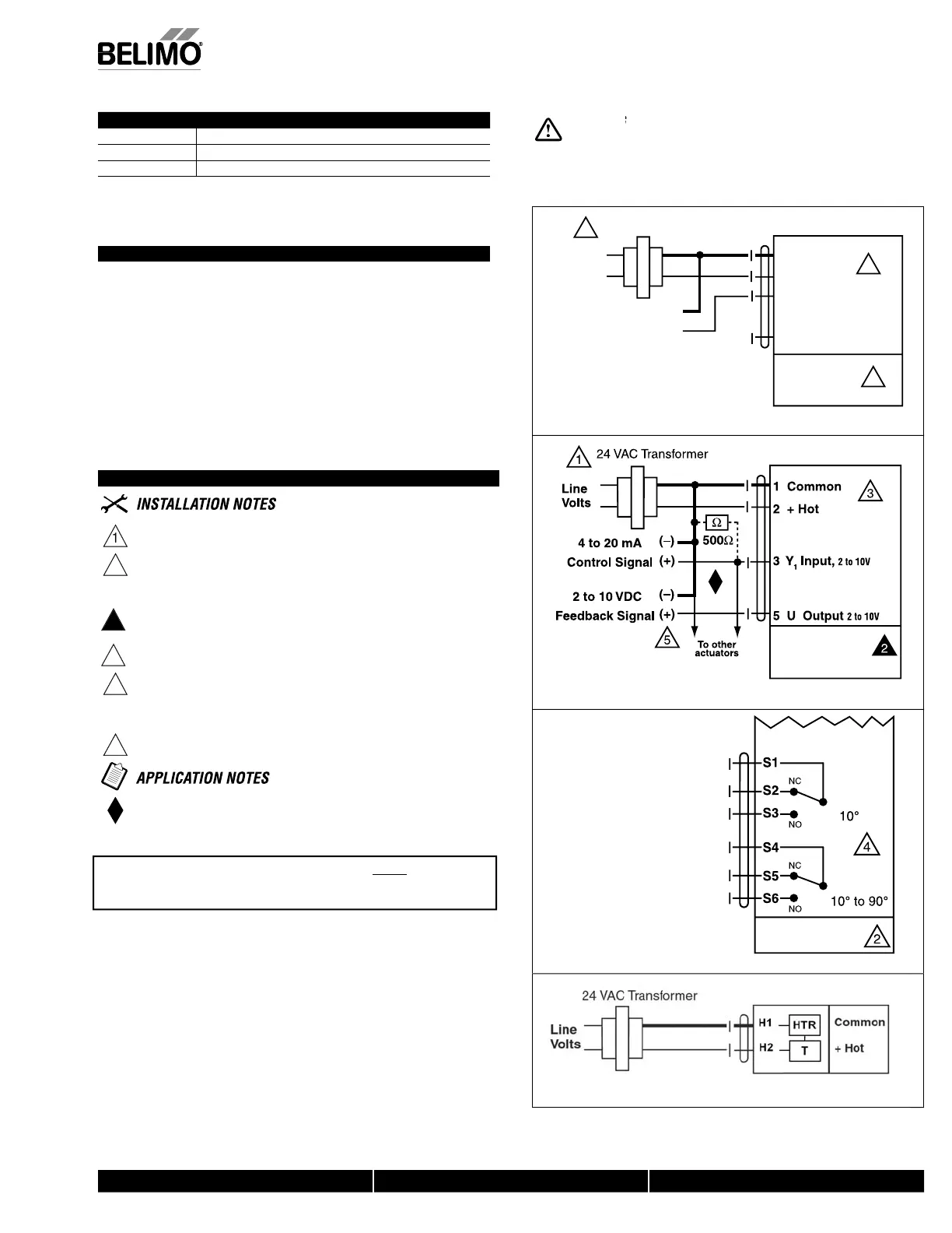
Wiring Diagrams
rov
e over
oa
rotect
on an
sconnect as re
u
re
A
TI
N Equipment Dama
e
Actuators ma
be connected in
arallel.
ower consum
t
on an
n
ut
m
e
ance must
e o
serve
.
2
p to 4 actuators may
e connecte
n para
e
.
t
4 actuator
wired to one 500
resistor. Power consum
tion must be observed
Actuator may also be powered by 24 VD
or end position indication, interlock control, fan startup, etc., AFB24-SR-S N4
H
,
AFX24-
R-
N4 incorporates two built-in auxiliary switches: 2 x
PDT, 3
0.5A) @250 VAC, UL Approved, one switch is fi xed at +10°, one is adjustable
0° to 90°
nly connect common to ne
.
–
le
of control circuits
h
Z
-R
1
res
stor converts t
e 4 to 20 m
contro
s
gna
t
2 t
1
VD
Live Electrical Components!
Durin
installation, testin
, servicin
and troubleshootin
o
this product, it may be
necessar
to work with live electrical com
onents. Have a
uali
ed licensed electrician or other
individual who has been properly trained in handling live electrical components perform these
tasks. Failure to follow all electrical safety precautions when exposed to live electrical compo
nents could result in death or serious in
ury
Control Signal
(+)
2 to 10 VDC
(–)
1 Common
2 + Hot
3 Y
1
Input,
2 to 10V
5 U Output
2 to 10V
1
2
3
24 VAC Transformer
AFB24-SR N4(H)
AFB24-SR-S N4(H)
AFX24-SR N4
AFX24-SR-S N4
Line
Volts
W068_AFB24-SR_N
t
10 VDC c
ntr
l
AFB24-SR N4(H)
AFB24-SR-S N4(H)
AFX24-SR N4
AFX24-SR-S N4
W069_AFB24-SR_N4
to 20 mA control with 2 to 10 VDC feedback out
u
AFB24-SR-S N4(H)
AFX24-SR-S N4
W064_AFB24_SR_-S_N
Aux
l
ary sw
tche
K-AF-NF N4H 24V h
t
r
4
t
r
TTENTION
AFB24-SR
-S
N4
H
and AFX24-SR
-S
N4 cann
be tandem
ounted on the same damper or valve shaft.
nly
n
ff and MFT AF models can be
sed
or tandem mount a
lications.
N40103 - 09/11 - Subject to change. © Belimo Aircontrols (USA), Inc.
 Loading...


