800-543-9038 USA 866-805-7089 CANADA 203-791-8396 LATIN AMERICA / CARIBBEAN
2
AFB24-MFT, AFB24-MFT-S, AFX24-MFT, AFX24-MFT-S
roportional,
prin
Return, 24 V, Multi-Function Technolo
AFB24-MFT-S
AFX24-MFT-S
Auxiliary Switches for AFB24-MFT-S, AFX24-MFT-
W600_AFB_AF
W399_0
D
4-2
mA
399_0
W399_08
W399_08
loat
ng Po
nt contro
Accessories
8-25
haft extensio
-
Dam
er
osition indicator
-
rank arm
-
Universal clamp
or up to 1.05” dia jacksha
ts
F-
onduit fittin
oo
-0
mm an
10 mm wrenc
Z
-1
Universal mounting bracket
ZG-10
n
versa
mount
n
rac
et
Z
-1
Multiple actuator mounting bracke
Z
-118 Mounting bracket for Barber
olman
MA 3..
4.., Hone
well
o
or
or
o
nso
eries 100 replacement or new crank
arm type
nsta
at
on
Z
-AFB
rank arm adaptor kit
Z
-AFB118
rank arm adaptor kit
ZS-100 Weather shield
metal
Z
-1
Weather shield (polycarbonate
ZS-26
xplosion-proof housin
Z
-
EMA 4X housin
N
TE
When using AFB24-MFT, AFB24-MFT-S, AFX24-MFT and AFX24-MFT-S actuators, only use
ccessories listed on this page.
For actuator wiring information and diagrams, refer to Belimo Wiring
uide
Typical Specification
Sprin
return control damper actuators shall be direct coupled type which require no
rank arm and linka
e and be capable of direct mountin
to a
ackshaft up to a 1.05”
diameter. The actuator must
rovide
ro
ortional dam
er control in res
onse to a 2 to
10 VDC or, with the addition of a 50
resistor, a 4 to 20 mA control in
ut from an
lectronic controller or positioner. The actuators must be desi
ned so that they may be
sed for either clockwise or counterclockwise fail-safe o
eration. Actuators shall use
a brushless D
motor controlled b
a micro
rocessor and be
rotected from overload
at all angles of rotation. Run time shall be constant, and independent of torque. A 2 to
10 VDC feedback signal shall be provided for position feedback. Actuators shall be
ULus A
roved and have a 5
ear warrant
, and be manufactured under ISO 9001
International Qualit
Control Standards. Actuators shall be as manufactured b
Belimo.
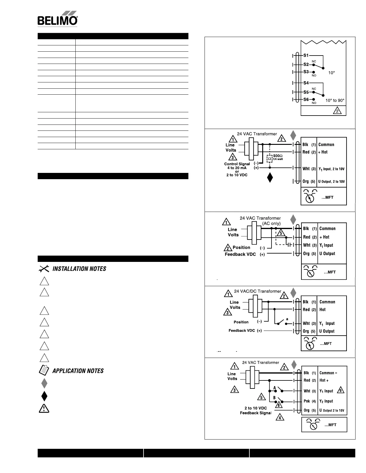
Wiring Diagrams
1
rov
e over
oa
protect
on an
sconnect as requ
re
2
AUTI
N
qu
pment
amage
Actuators may be connected in parallel i
not mechanically mounted to the same
sha
t. Power consum
tion and in
ut im
edance must be observed.
Actuators may also be powered by 24 VD
.
osition
eedback cannot be used with Triac sink controller.
he actuator internal common re
erence is not compatible.
ontrol si
nal may be pulsed from either the Hot
source
or the
ommon (sink) 24 VA
line
ontact closures A & B also can be triacs
A & B should both be closed
or triac source and open
or triac sink
9
r tri
ink th
mm
n
nn
ti
n
r
m th
t
t
r
t
nn
t
t
th
h
t
nn
ti
n
th
ntr
ll
r
Meets UL requirements without the need o
an electrical
round
nn
ti
n
h
Z
-R
1
Ω resistor may be used.
ARNIN
Live Electrical Com
onents
Durin
installation, testin
, servicin
and troubleshootin
of this product, it may be
necessary to work with live electrical components. Have a qualifi ed licensed electrician
or ot
er
n
v
ua
w
o
as
een proper
y tra
ne
n
an
ng
ve e
ectr
ca
components
perform these tasks. Failure to follow all electrical safety precautions when exposed to
live electrical components could result in death or serious in
ury
N40103 - 09/11 - Subject to change. © Belimo Aircontrols (USA), Inc.
 Loading...


