800-543-9038 USA 866-805-7089 CANADA 203-791-8396 LATIN AMERICA / CARIBBEAN
AFB24-MFT N4(H), AFB24-MFT-S N4(H), AFX24-MFT N4, AFX24-MFT-S N4
EMA 4, Proportional, Sprin
Return, Direct Coupled, 24V, Multi-Function Technolo
y
Technical Data AFB24-MFT N4(H), AFB24-MFT-S N4(H),
AFX24-MFT N4, AFX24-MFT-S N4
ower supp
y 24 VAC, +/- 20%, 50/60 H
24 VD
, +20%
-10%
owe
runn
n
7.5 W / heater 25 W
consum
tio
holdin
3 W
Transformer sizing 10 VA (
lass 2 power source)
heater 25 V
Electrical connectio
AFB... N4 3 ft, 18
A appliance cable, 1
2" conduit connecto
-
models: two 3 ft, 18 gauge appliance cables with
1
2” conduit connector
heater
N4H
terminal block, 26-16 G
...
ft
1m
, 10 ft
3m
or 16 ft
5m
18
A appliance
cables, with 1/2” conduit connector
-S m
dels: two
t [1m], 10
t [3m] or
16 ft
5m
appliance cables with 1/2" conduit
connector
Overload protectio
electronic throu
hout 0 to 95° rotatio
Operatin
ran
e Y* 2 to 10 VDC, 4 to 20 mA
default
variable
VD
, PWM, floatin
point, on
off
Input impedanc
100 k
for 2 to 10 VDC
0.1 mA
500 Ω for 4 to 20 mA
for PWM, floatin
point and on
off control
Feedback output U
2 to 10 VD
, 0.5 mA ma
orque
n
mum 180
n-
20
m
Direction o
spr
n
reversible with cw
ccw mounting inside housing
otation
motor reversible with built-in switch
ec
an
ca
an
le of rotation
95°
a
usta
e w
t
mec
an
ca
en
stop, 35° to 95°
Runnin
time
otor* 150 seconds
default
, variable
70 to 220 seconds
sprin
<20 sec @ -4°F to 122°F
-20°C to 50°C
;
<60 sec @ -22°F
-30°C
pr
ng
w
t
eater
<20 sec
-4°F to 122°F [-20°
to 50°
];
<60 sec
-49°F [-45°
An
le o
Rotation
ada
tation
o
de
ault
Override control*
in position = 0
. pos
t
on = 50%
ax. pos
t
on = 100
P
iti
n in
i
ti
visual indicator, 0° to 95
0°
s spr
n
return pos
t
on
n
l
v
rri
5 mm hex crank
₁₆" Allen
, supplied
um
ty
ax. 95%
non-con
ens
n
Ambient temperatur
-22°F to 122°F
-30°
to 50°
ith heater -49°F to 122°F
-45°C to 50°C
tora
e temperature -40°F to 176°F
-40°C to 80°C
Housin
UL T
e 4, NEMA 4, IP66
ous
ng mater
a
po
ycar
onate
N
i
l
v
0dB
A
motor @ 150 seconds, run time dependen
2
spr
n
return
A
ency listin
s
cULus acc. to UL60730-1A/-2-14, CAN/CSA E60730
1:02,
E acc. to 2004
108
E
& 2006
95
E
ualit
standard I
9001
ervicing
int
n
n
r
Wei
h
9.7 lbs.
4.4 k
, 10 lbs.
4.5 k
with switche
10.5
s
4.8
g
w
t
eater
* Variable when confi
ured with MFT option
Rated Impulse Voltage 800V, Type of action 1.AA (1.AA.B for -S version), Control Pollution Degree 4.
Programmed
or 70 sec motor run time. At 150 sec motor run time, trans
ormer sizing
is 8.5 VA and power consumption is 6 W running / 3 W holding.
FB24-MFT-
N4(H), AFX24-MFT-
N
ux
ary sw
tc
es 2 x
PDT 3A (0.5A)
250 VA
, UL approve
one set at +10°, one a
usta
e 10° to 90
Torque min. 180 in-lb
or control o
damper sur
aces up to 45 sq
t.
A
l
cat
o
For proportional modulation of dampers in HVA
systems. Actuator sizing should be
done in accordance with the damper manu
acturer’s speci
cations.
The actuator is mounted directly to a damper shaft up to 1.05" in diameter by means
its universal clamp.
The default parameters for 2 to 10 VD
applications of the …MFT actuator are
ssigned during manu
acturing. I
necessary, custom versions o
the actuators can
e ordered. The parameters can be chan
ed by two means: pre-set and custom
confi gurations from Belimo or on-site confi gurations using the Belimo PC-Tool
software
peratio
The actuator is not provided with and does not require any limit switches, but is
electronically protected a
ainst overload. The anti-rotation strap supplied with the
ctuator will
revent lateral movement
The AFB24-MFT N4
H
, AFB24-MFT-S N4
H
, AFX24-MFT N4, AFX24-MFT-S N4
rovides 95° of rotation and a visual indicator indicates
osition of the actuator. When
eac
ng t
e
amper or actuator en
pos
t
on, t
e actuator automat
ca
y stops.
e
ctuator can be manually operated with the manual crank that is supplied a
ter the
cover is removed.
The AFB24-MFT N4(H), AFB24-MFT-
N4(H), AFX24-MFT N4, AFX24-MFT-
N4
ctuators use a brushless DC motor, which is controlled by an Application Specifi c
Inte
rated Circuit
ASIC
. The ASIC monitors and controls the actuator’s rotation and
rovides a digital rotation sensing (DRS) function to prevent damage to the actuator in
stall condition.Power consumption is reduced in holdin
mode
dd-on auxiliar
switches or feedback
otentiometers are easil
fastened directl
nto the actuator body
or si
nalin
and switchin
unctions.
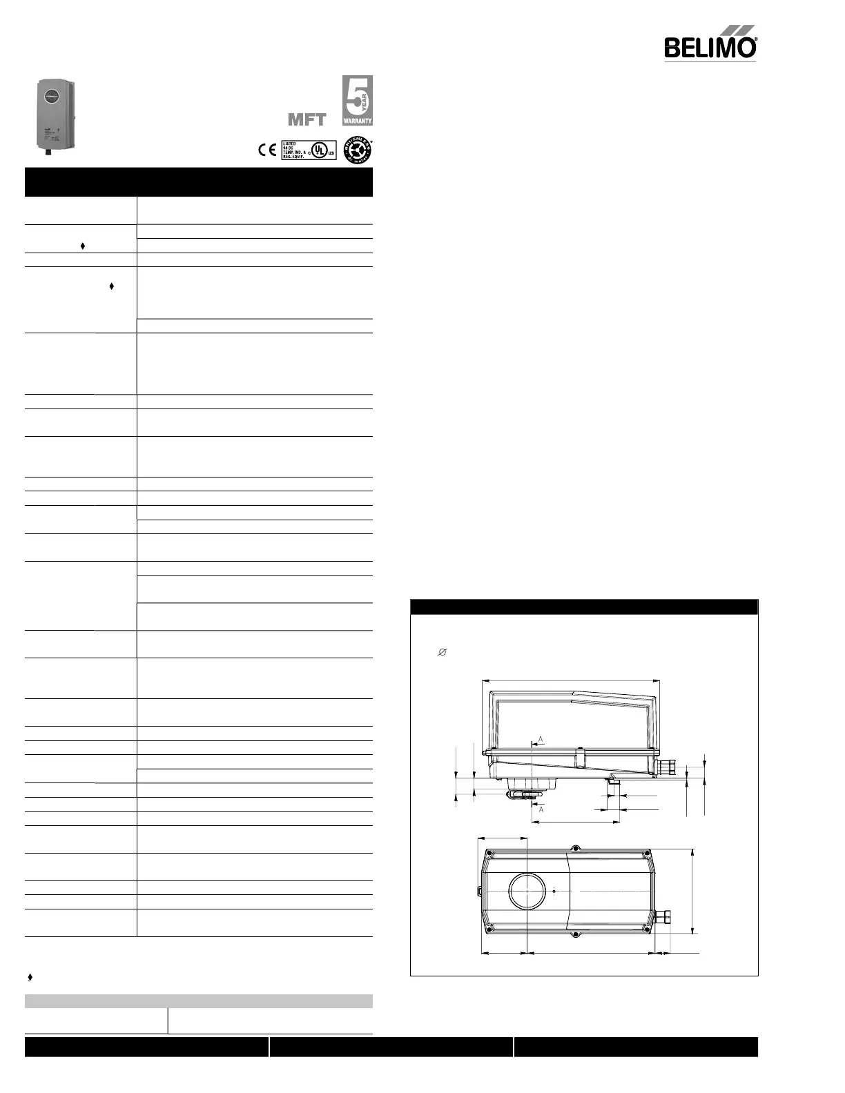
Dimensions (inches [mm])
6.77” [172]
Clamp Congurations
1/2” Field Selectable 3/4” Centered 1.05” Centered
(Default) (Field Selectable)
12.99” [330]
6.45” [163.9]
0.39” [10]
0.92” [23.4]
3.62” [92.1]
9.37” [238] 1.12” [28.5]
3.36” [85.2]
3.5” [0.14]
0.81” [20.5]
1.17” [29.8]
0.79” [20]
312_Confi
N40103 - 09/11 - Subject to change. © Belimo Aircontrols (USA), Inc
 Loading...


