Accessories
IRM-100 Input scaling module
KH8 Universal crankarm
KG10 Ball Joint
NSV24 Battery back-up module
P… Feedback potentiometer
PTA-250 Pulse width modulation interface
SGA24 Min. and/or manual positioner in NEMA 4 housing
SGF24 Min. and/or man. positioner for flush panel mount
S1,S2 Auxiliary switch
Tool-06 8mm and 10 mm wrench
ZAD24 Digital position indication
ZDB-GM Angle of rotation limiter (Series 2)
ZG-H2 Actuator operator handle
ZG-GM2 Crankarm adaptor kit
ZG-R01 500Ω resistor for 4 to 20 mA
ZG-100 Universal mounting bracket
ZG-101 Universal mounting bracket
ZG-102 Multiple actuator mounting bracket
ZG-103 Universal mounting bracket
ZG-104 Universal mounting bracket
ZS-100 Weather shield (metal)
ZS-150 Weather shield (polycarbonate)
ZS-260 Explosion-proof housing
ZS-300 NEMA 4X housing
NOTE: When using GM24-SR US actuators, use only
the accessories listed on this page.
Wiring diagrams
GM24-SR US - Typical Specification:
Control damper actuators shall be electronic direct coupled
type which require no crankarm and linkage. Actuators shall
be UL listed and CSA certified, have a 2 year warranty, and
be manufactured under ISO 9001 International Quality Control
Standards. Actuators shall have reversing switch and gear
disengagement button on the cover. Actuators shall use a
brushless DC motor and be protected from overload at all
angles of rotation. Run time shall be constant and independ-
ent of torque. The actuator must provide proportional damper
control in response to a 2 to 10 VDC or, with the addition of a
500Ω resistor, a 4 to 20 mA control input from an electronic
controller or positioner. A 2 to 10 VDC feedback signal shall
be provided for position indication or master-slave applica-
tions. Actuators shall be as manufactured by Belimo.
2
1
Provide overload protection and disconnect as required.
Actuators may be connected in parallel. Power con-
sumption and input impedance must be observed.
4 to 20 mA control of GM24-SR US with 2 to 10 VDC feed-
back output.
0 to 10 VDC control of GM24-SR US
2
1
3
Provide overload protection and disconnect as required.
Connect actuator common (wire 1) to negative (–) leg
of control circuits only.
Up to 4 actuators may be connected in parallel. With 4
actuators wired to one 500Ω resistor, a +2% shift of
control signal may be required. Power consumption
must be observed.
The 500Ω resistor converts the 4 to 20 mA control sig-
nal to 2 to 10 VDC.
Actuator may also be powered by 24 VDC.
4
5
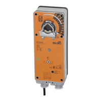
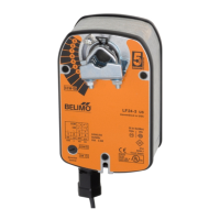
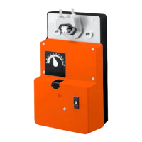
GM24-SR US
Proportional damper actuator, non-spring return, direct coupled,
24 V for 2 to 10 VDC and 4 to 20 mA control signal.
Multiple actuators mounted to shaft
Model Maximum quantity per shaft
GM24 US 2
GM24-SR US 2
 Loading...