60
V4. 12. 2010
.
Subject to modification
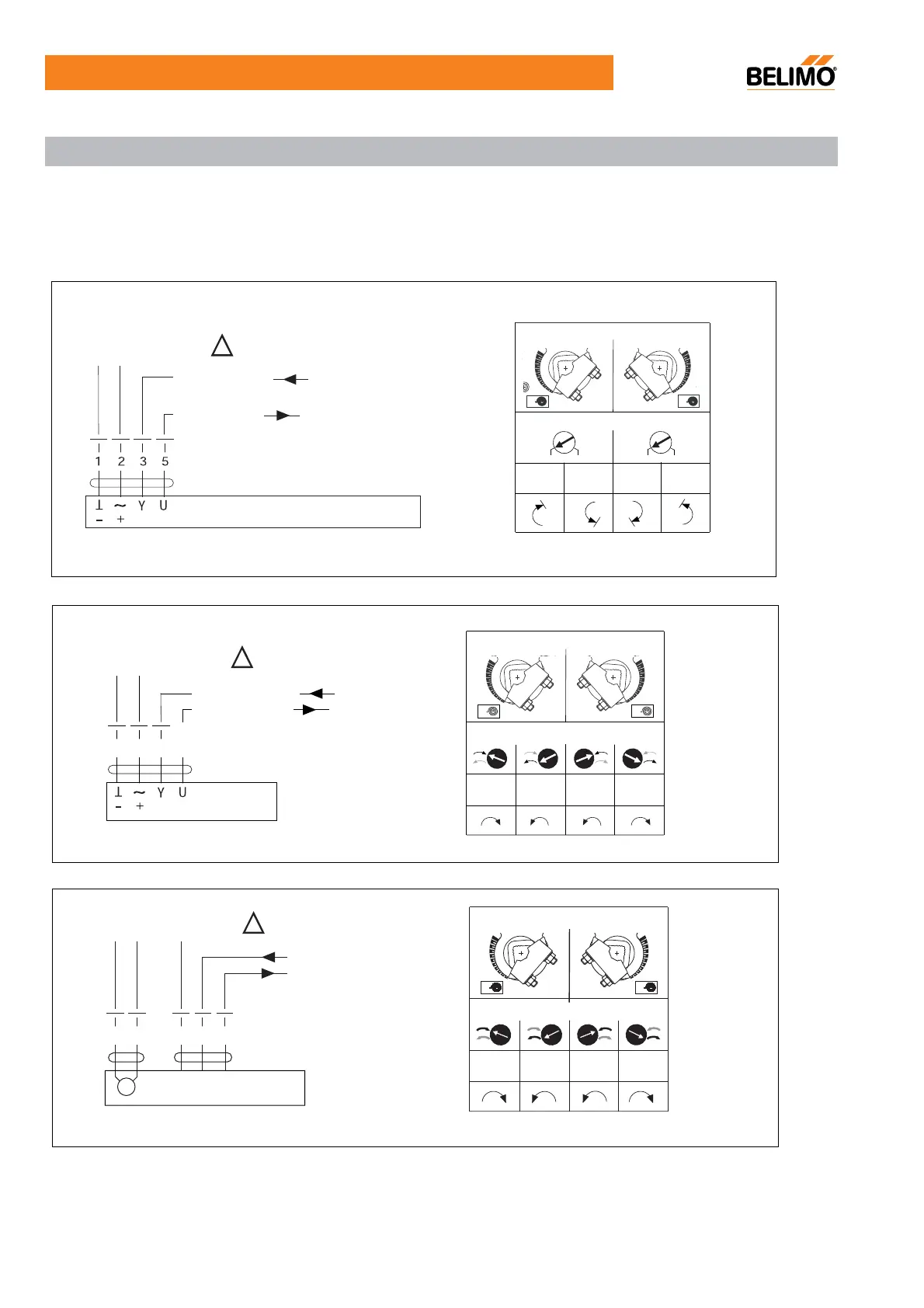
Wiring diagram: Modulating actuators
AC/DC 24V
AC/DC 24V
Y DC 2(0)...10V
U DC 2...10V
LF24-SR, NFU24-SR, SFU24-SR
L
0
.2
.4
.6
.8
1
R
0
.2
.4
.6
.8
1
with
Y = 0
with
Y = 0
with
Y = 0
with
Y = 0
with
Y = 0
with
Y = 0
with
Y = 0
with
Y = 0
with
Y = 0
with
Y = 0
with
Y = 0
with
Y = 0
R
L
Reversing switch
R
L
Mounting side
Y
U
1
32
5
DC 2(0)…1V
DC 2…10V
– +
T
T
~
– +
T
~
L
0
.2
.4
.6
.8
1
R
0
.2
.4
.6
.8
1
Mounting side
Reversing switch
TF24-SR
TF230-SR
Connect via safety
isolating transformer
Connect via safety
isolating transformer
Notes:
•ΓConnection via safety isolating transformer.
•ΓParallel connection of several actuators is possible.
•ΓPower consumption must be observed.
!
!
Connect via safety
isolating transformer
!
N
1
2
L
M
1 3 5
Y
U
DC 2(0)…10V
DC 2…10V
/
5
Mounting side
Reversing switch
Wiring diagrams—Mechanical Fail-Safe Damper Actuator

 Loading...