Do you have a question about the Belimo LMB24-3 and is the answer not in the manual?
Feature summary table for different LM series actuators, covering key specifications.
Highlights of the actuator's advantages, including accuracy and ease of use.
Detailed specifications for the LMB24-3 actuator, including electrical and performance data.
Description of how the LMB24-3 is used in HVAC systems and damper control.
Explanation of the LMB24-3 actuator's features, overload protection, and manual override.
Physical measurements and size details of the LMB24-3 actuator.
List of optional accessories available for the LMB24-3 actuator.
General technical overview and compliance information for the LMB24-3.
Electrical connection diagrams for LMB24-3 On/Off and Floating Point control.
Detailed specifications for the LMCB24-3 actuator, including electrical and performance data.
Description of how the LMCB24-3 is used in HVAC systems and damper control.
Explanation of the LMCB24-3 actuator's features, overload protection, and manual override.
Physical measurements and size details of the LMCB24-3 actuator.
List of optional accessories available for the LMCB24-3 actuator.
General technical overview and compliance information for the LMCB24-3.
Electrical connection diagrams for LMCB24-3 On/Off and Floating Point control.
Detailed specifications for the LMX24-3 actuator, including electrical and performance data.
Description of how the LMX24-3 is used in HVAC systems and damper control.
Explanation of the LMX24-3 actuator's features, overload protection, and manual override.
Physical measurements and size details of the LMX24-3 actuator.
List of optional accessories available for the LMX24-3 actuator.
General technical overview and compliance information for the LMX24-3.
Electrical connection diagrams for LMX24-3 On/Off and Floating Point control.
Detailed specifications for the LMX120-3 actuator, including electrical and performance data.
Description of how the LMX120-3 is used in HVAC systems and damper control.
Explanation of the LMX120-3 actuator's features, overload protection, and manual override.
Physical measurements and size details of the LMX120-3 actuator.
List of optional accessories available for the LMX120-3 actuator.
General technical overview and compliance information for the LMX120-3.
Electrical connection diagrams for LMX120-3 On/Off and Floating Point control.
Detailed specifications for the LMB24-SR actuator, including control and performance data.
Description of how the LMB24-SR is used for proportional modulation in HVAC systems.
Explanation of the LMB24-SR actuator's proportional control, overload protection, and override.
Physical measurements and size details of the LMB24-SR actuator.
List of optional accessories available for the LMB24-SR actuator.
General technical overview and compliance information for the LMB24-SR.
Electrical connection diagrams for LMB24-SR 2-10 VDC and 4-20 mA control.
Detailed specifications for the LMCB24-SR actuator, including control and performance data.
Description of how the LMCB24-SR is used for proportional modulation in HVAC systems.
Explanation of the LMCB24-SR actuator's proportional control, overload protection, and override.
Physical measurements and size details of the LMCB24-SR actuator.
List of optional accessories available for the LMCB24-SR actuator.
General technical overview and compliance information for the LMCB24-SR.
Electrical connection diagrams for LMCB24-SR 2-10 VDC and 4-20 mA control.
Detailed specifications for the LMX24-SR actuator, including control and performance data.
Description of how the LMX24-SR is used for proportional modulation in HVAC systems.
Explanation of the LMX24-SR actuator's proportional control, overload protection, and override.
Physical measurements and size details of the LMX24-SR actuator.
List of optional accessories available for the LMX24-SR actuator.
General technical overview and compliance information for the LMX24-SR.
Electrical connection diagrams for LMX24-SR 2-10 VDC and 4-20 mA control.
Detailed specifications for the LMX120-SR actuator, including control and performance data.
Description of how the LMX120-SR is used for proportional modulation in HVAC systems.
Explanation of the LMX120-SR actuator's proportional control, overload protection, and override.
Physical measurements and size details of the LMX120-SR actuator.
List of optional accessories available for the LMX120-SR actuator.
General technical overview and compliance information for the LMX120-SR.
Electrical connection diagrams for LMX120-SR 2-10 VDC and 4-20 mA control.
Detailed specifications for the LMB(X)24-MFT actuator, including control and performance data.
Description of how the LMB(X)24-MFT is used for proportional modulation in HVAC systems.
Explanation of the LMB(X)24-MFT actuator's proportional control, overload protection, and override.
Physical measurements and size details of the LMB(X)24-MFT actuator.
List of optional accessories available for the LMB(X)24-MFT actuator.
General technical overview and compliance information for the LMB(X)24-MFT.
Electrical connection diagrams for LMB(X)24-MFT with different control types.
Detailed specifications for the LMX24-MFT95 actuator, including control and performance data.
Description of how the LMX24-MFT95 is used for proportional modulation in HVAC systems.
Explanation of the LMX24-MFT95 actuator's proportional control, overload protection, and override.
Physical measurements and size details of the LMX24-MFT95 actuator.
List of optional accessories available for the LMX24-MFT95 actuator.
General technical overview and compliance information for the LMX24-MFT95.
Electrical connection diagrams for LMX24-MFT95 with different control types.
Detailed specifications for the LMX24-PC actuator, including control and performance data.
Description of how the LMX24-PC is used for proportional modulation in HVAC systems.
Explanation of the LMX24-PC actuator's proportional control, overload protection, and override.
Physical measurements and size details of the LMX24-PC actuator.
List of optional accessories available for the LMX24-PC actuator.
General technical overview and compliance information for the LMX24-PC.
Electrical connection diagrams for LMX24-PC 0-20V Phasecut control.
Guidelines for mounting actuators in dry environments and ordering dampers.
Guidance on selecting the correct actuator based on damper torque and size.
Visual guide for mechanical mounting of actuators using quick-mount systems.
Step-by-step instructions for standard actuator mounting.
Procedure for testing actuator installation before applying power.
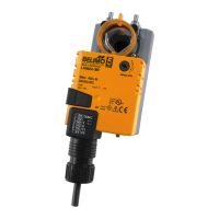
The Belimo LM Series Direct Coupled Actuator is a versatile and powerful device designed for controlling dampers in HVAC systems. It offers a compact package with a minimum torque of 45 in-lb, suitable for damper areas up to 11 sq-ft, based on a 4 in-lb/ft² damper torque loading for parallel blade dampers without edge seals.
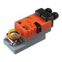
The LM Series actuators are electronic direct-coupled devices that do not require crankarms or linkages, mounting directly onto a damper shaft. They are available in various control types, including On/Off, Floating Point, Proportional (2 to 10 VDC or 4 to 20 mA), and Phasecut (0 to 20V). The actuators utilize a sensorless Brushless DC motor, controlled by an Application Specific Integrated Circuit (ASIC). This ASIC monitors and controls the actuator's rotation, incorporating a Digital Rotation Sensing (DRS) function to prevent damage in a stall condition. Power consumption is reduced in holding mode.
The actuators provide a 95° angle of rotation, which can be adjusted with mechanical stops. A visual indicator shows the actuator's position. When the damper or actuator reaches an end position, the actuator automatically stops. The gears can be manually disengaged using a button on the actuator cover. Overload protection is electronic throughout the entire 0 to 95° rotation range, ensuring the actuator is protected without the need for limit switches. An anti-rotation strap is supplied to prevent lateral movement.
Some models, like the LMB24-3-S, include a built-in auxiliary switch (SPDT, 3A @ 250 VAC) for safety interfacing or signaling, such as fan start-up. This switch is adjustable from 0 to 95° and is double insulated, eliminating the need for an electrical ground connection. For proportional control models (e.g., LMB24-SR, LMCB24-SR, LMX24-SR, LMX120-SR), a 2 to 10 VDC feedback signal is provided for position indication or master-slave applications. With the addition of a 500Ω resistor, these models can also accept a 4 to 20 mA control input.
Multi-Function Technology (MFT) models (LMB(X)24-MFT, LMX24-MFT95) offer enhanced flexibility. Their default parameters are set for 2 to 10 VDC applications during manufacturing, but custom versions can be ordered. Parameters can be changed via pre-set and custom configurations from Belimo or on-site using the Belimo PC-Tool software. The LMX24-MFT95 specifically supports Honeywell Electronic Series 90 (0 to 135Ω) input.
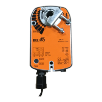
The LM Series actuators are designed for ease of installation and operation. They self-center on 5/8" jackshafts with the standard clamp, and shafts up to 3/4" diameter can be accommodated with an accessory clamp (K-LM20). The direct coupling mechanism cuts labor costs. A clear position indicator allows for easy checking of the damper position. The actuators are overload-proof throughout their rotation, eliminating concerns about burnout.
Mechanical stops allow for easy adjustment of the angle of rotation. For models with a reversing switch, the control direction can be changed simply. A readily accessible manual override button helps in pre-tensioning damper blades. For basic models, a standard 3ft plenum-rated cable and conduit connector are provided. The flexible line of actuators allows for selection of clamps, electrical connections, and running times to fit specific applications.
Auxiliary switches and feedback potentiometers can be easily fastened directly onto the actuator body for signaling and switching functions. For new construction, it is recommended to order dampers with extended shafts to allow space for mounting the actuator. When replacing existing gear train actuators, direct mounting onto the damper shaft is preferred. If the damper shaft is not accessible, the non-spring return actuator can be mounted with a crankarm kit and a mounting bracket.
For installation, the damper shaft should be turned until the blades are fully closed. The actuator's universal clamp is then slipped over the damper shaft, ensuring access to the duct and controls. The two nuts on the universal clamp are hand-tightened. The gear train is disengaged by pressing the manual override button, and the clamp is rotated until centered. The anti-rotation strap is slid up under the actuator, engaging the center cutout, and bent as needed to support the rear of the actuator, then secured to ductwork with self-tapping screws. The nuts on the universal clamp are loosened, and the clamp is rotated to about 5° from the closed position (1/16 to 1/8" between stop and clamp) to pre-load the damper. The nuts are then tightened with a 10 mm wrench to the required torque. Finally, the reflective position indicator is snapped on, and end-stops are adjusted if needed.
The LM Series actuators are designed for maintenance-free operation. Components are tested before assembly, and every product is tested before shipment, contributing to a long service life. The robust design, based on over 30 years of direct coupled actuator design, ensures durability.
For optimal performance and longevity, Belimo actuators with NEMA 1 or NEMA 2 ratings should be mounted indoors in a dry, relatively clean environment, free from corrosive fumes. If outdoor mounting is necessary, a protective enclosure must be used to shield the actuator.
The pre-loading step during installation ensures that when the actuator is powered and sent to the closed position, it applies full torque to the shaft, compressing edge and blade seals. This helps the damper meet its leakage rating and prevents damage to the actuator.
Testing the installation without power involves disengaging the gear train with the manual override button and moving the shaft from closed to open to closed. This ensures there is no binding and that the damper fully opens and closes with 5° of actuator stroke left. Any problems identified should be corrected and retested.
| Power Supply | 24 V AC/DC |
|---|---|
| Protection Class | IP54 |
| Angle of Rotation | 90° |
| Housing Material | Plastic |
| Control Type | On/Off |
| Temperature Range | -30…50°C |
| Connection | Cable |