71
J20741 - Subject to change. © Belimo Aircontrols (USA), Inc.
LF
LF24-3 (-S) US
On-off, Spring Return Fail-Safe, Reversible, Floating Point, 24V
Accessories
AV 10-18 Shaft extension (K6-1 is required)
IND-LF Damper position indicator
K6-1 Universal clamp for up to 3/4” diameter shafts
KH-LF Crankarm for up to 1/2” round shaft
Tool-06 8mm and 10 mm wrench
ZG-LF2 Crankarm adaptor kit for LF
ZG-112 Mounting bracket for Honeywell Mod IV, M6415
type actuators, and new installations
ZG-LF112 Crankarm adaptor kit for Honeywell Mod IV,
M6415 type actuators, and new installations
ZS-100 Weather shield (metal)
ZS-150 Weather shield (polycarbonate)
ZS-260 Explosion-proof housing
Note: When using LF24-3 (-S) US actuators, only use
accessories listed on this page.
For Actuator Wiring Information and Diagrams,
Please See Belimo Wiring Guide (pg 349).
LF24-3 (-S) US Typical Specification
Floating point, on-off spring return damper actuators shall be direct cou-
pled type which require no crankarm and linkage and be capable of direct
mounting to a shaft up to a 3/4” diameter and center a 1/2” shaft. The actu-
ators must be designed so that they may be used for either clockwise or
counterclockwise fail-safe operation. Actuators shall have an external
direction of rotation switch to reverse control logic. Actuators shall use a
brushless DC motor and be protected from overload at all angles of rota-
tion. If required, 1 SPDT auxiliary switch shall be provided having the
capability of being adjustable. Actuators with auxiliary switch must be
constructed to meet the requirements for Double Insulation so an elec-
trical ground is not required to meet agency listings. Run time shall be
constant and independent of torque. Actuators shall be UL listed and CSA
certified, have a 5 year warranty, and be manufactured under ISO 9001
International Quality Control Standards. Actuators shall be as manufac-
tured by Belimo.
28
3
24 VAC Transformer
a open
a closed
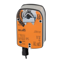
The indication of direction
is valid for switch position CW.
Blk (1) Common
Red (2) +
Wht (3) +
Grn (4) +
LF24-3 (-S) US
CW CCW
a
Line
Volts
WARNING
Live Electrical Components!
During installation, testing,
servicing and troubleshooting
of this product, it maybe
necessary to work with live
electrical components. Have
a qualified licensed electrician
or other individual who has
been properly trained in
handling live electrical
components perform these
tasks. Failure to follow all
electrical safety precautions
when exposed to live electrical
components could result in
death or serious injury.
Line
Volts
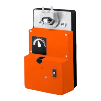
The indication of direction
is valid for switch position CW.
Blk (1) Common
Red (2) +
Wht (3) +
Grn (4) +
24 VAC Transformer
LF24-3 (-S) US
CW CCW
a
b
8
b
CCW
CW
stop
a
(3) (4)
stop stop stop
Installation Side
Direction of Rotation Switch
x
x
xx
x
x
x
x
xx
x
x
x
x
x
x
x
x
x
x
x
x
x
x
x
x
x
xx
x
x
xx
x
x
x
x
x
CW
CCW
Switch
Positions
CCW
CW
WARNING
Live Electrical Components!
During installation, testing,
servicing and troubleshooting
of this product, it maybe
necessary to work with live
electrical components. Have
a qualified licensed electrician
or other individual who has
been properly trained in
handling live electrical
components perform these
tasks. Failure to follow all
electrical safety precautions
when exposed to live electrical
components could result in
death or serious injury.
Wiring Diagrams
On-Off control of LF24-3 (-S) US
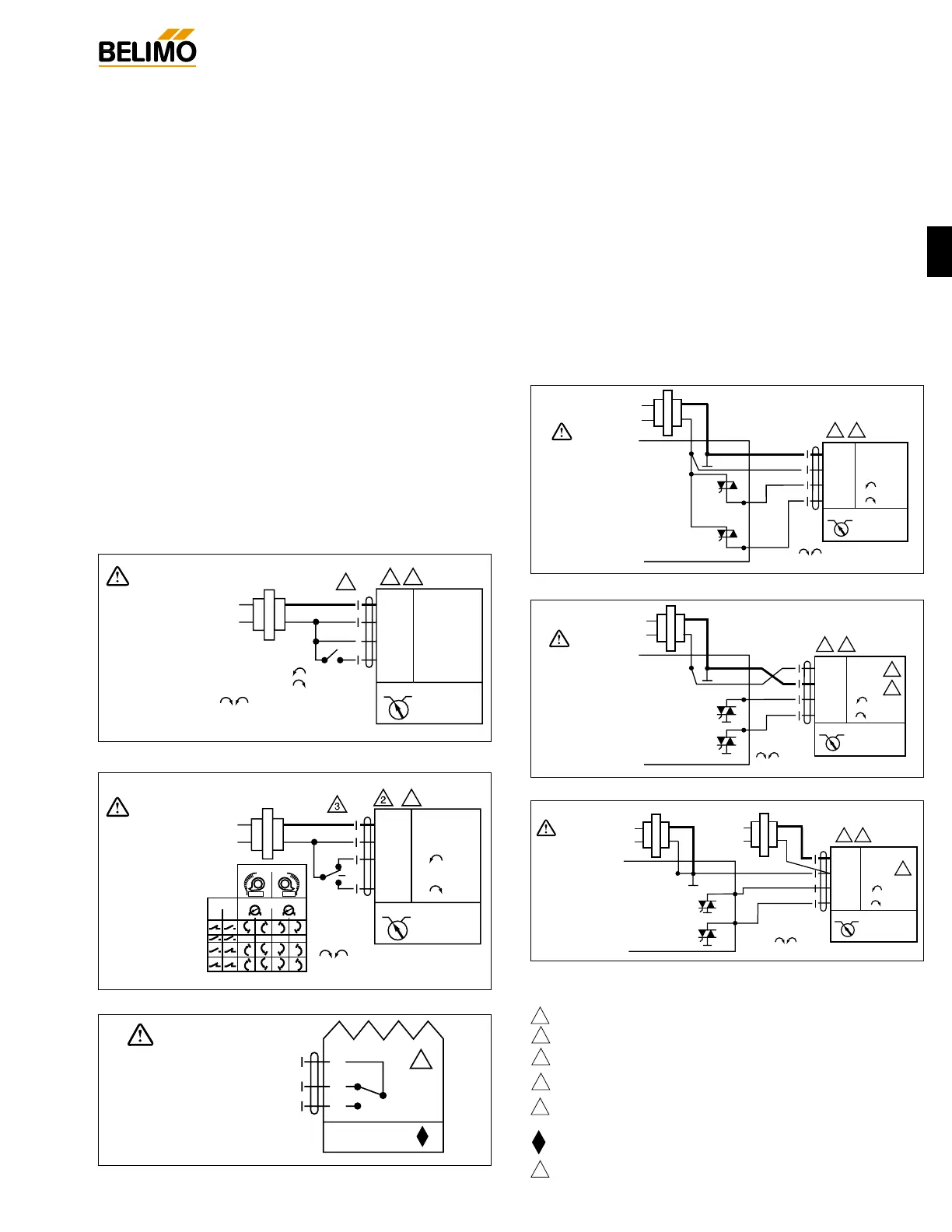
Triac source
Triac sink
Floating point control of LF24-3 (-S) US
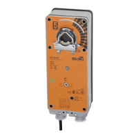
Auxiliary switch of LF24-3 (-S) US
Blk (1) Common
Red
(2) + Hot
Wht
(3) +
Grn
(4) +
ComHot
Controller
Line
Volts
CW CCW
LF24-3 (-S) US
The indication of direction is
valid for switch position CW.
2
24 VAC Transformer
8
WARNING
Live Electrical Components!
During installation, testing,
servicing and troubleshooting
of this product, it maybe
necessary to work with live
electrical components. Have
a qualified licensed electrician
or other individual who has
been properly trained in
handling live electrical
components perform these
tasks. Failure to follow all
electrical safety precautions
when exposed to live electrical
components could result in
death or serious injury.
Blk (1) Common
Red
(2) + Hot
Wht
(3) +
Grn
(4) +
ComHot
Controller
Line
Volts
CW CCW
LF24-3 (-S) US
The indication of direction is valid for switch position CW.
2
4
5
24 VAC Transformer
8
WARNING
Live Electrical Components!
During installation, testing,
servicing and troubleshooting
of this product, it maybe
necessary to work with live
electrical components. Have
a qualified licensed electrician
or other individual who has
been properly trained in
handling live electrical
components perform these
tasks. Failure to follow all
electrical safety precautions
when exposed to live electrical
components could result in
death or serious injury.
Triac sink with separate transformers
Blk (1) Common
Red
(2) + Hot
Wht
(3) +
Grn
(4) +
ComHot
Controller
Line
Volts
CW CCW
LF24-3 (-S) US
The indication of direction is valid for switch position CW.
2
5
24 VAC Transformer
Line
Volts
24 VAC Transformer
8
WARNING
Live Electrical Components!
During installation, testing,
servicing and troubleshooting
of this product, it maybe
necessary to work with live
electrical components. Have
a qualified licensed electrician
or other individual who has
been properly trained in
handling live electrical
components perform these
tasks. Failure to follow all
electrical safety precautions
when exposed to live electrical
components could result in
death or serious injury.
LF24-3-S US
6
S1
S2
S3
NC
NO
0° to 95°
WARNING
Live Electrical Components!
During installation, testing, servicing and
troubleshooting of this product, it maybe
necessary to work with live electrical
components. Have a qualified licensed
electrician or other individual who has been
properly trained in handling live electrical
components perform these tasks. Failure to
follow all electrical safety precautions when
exposed to live electrical components could
result in death or serious injury.
2
3
4
5
Actuators may be connected in parallel. Power consumption must be observed.
May also be powered by 24 VDC.
The Common connection from the actuator must be connected to the Hot con-
nection of the controller.
The actuator Hot must be connected to the control board Common.
For end position indication, interlock control, fan startup, etc., LF24-3-S US
LF120-S US and LF230-S US incorporate one built-in auxiliary switch: 1 x SPDT,
3A (0.5A) @250 VAC, UL listed, adjustable 0° to 95°.
Meets UL and CSA requirements without the need of an electrical ground connection.
Actuators with plenum rated cable do not have numbers on wires; use color
coded instead. Actuators with appliance rated cable use numbers.
6
8
Notes:
W053 W052
W051
W054W055W056
 Loading...