89
J20741 - Subject to change. © Belimo Aircontrols (USA), Inc.
LF
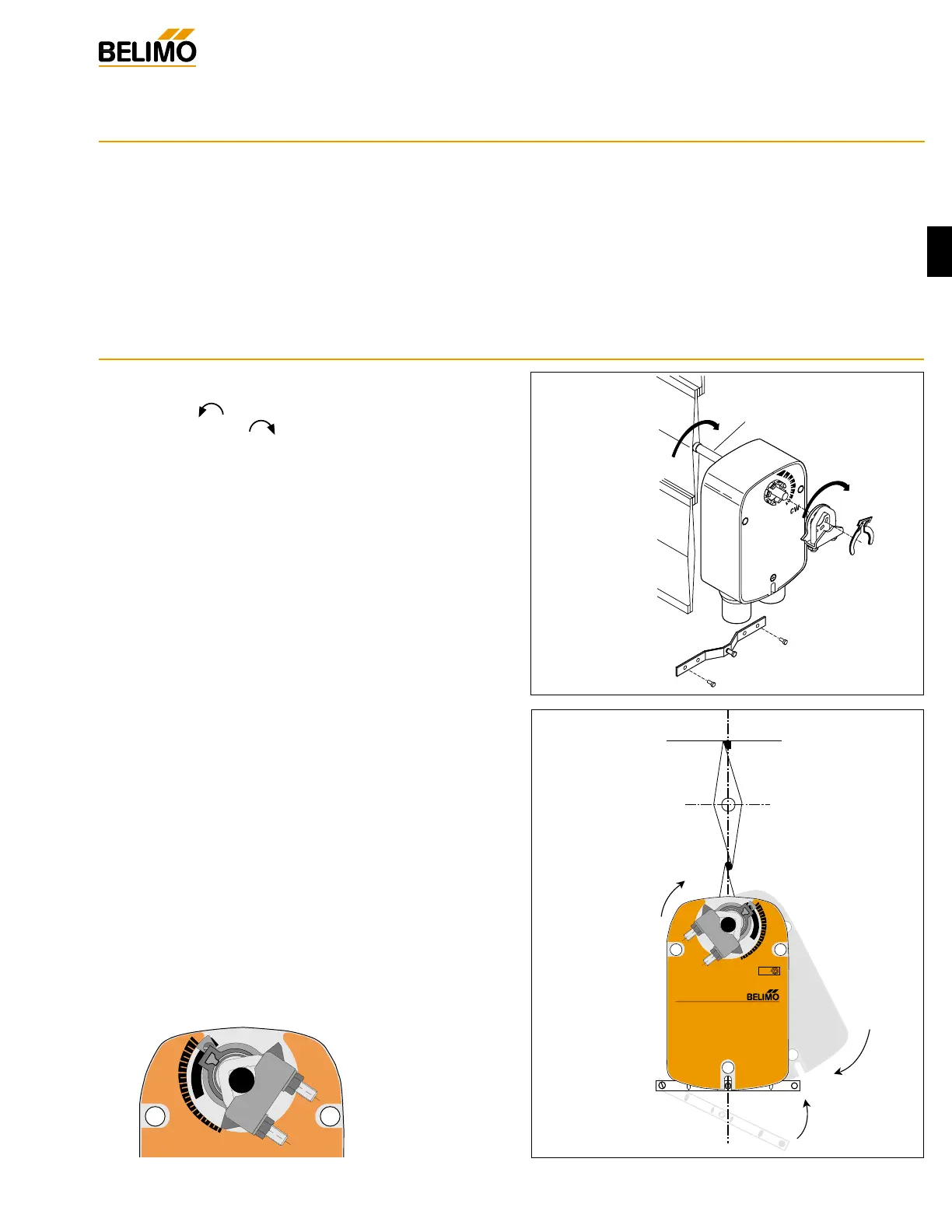
1. See Fig. B. Manually move the damper to the fail-safe
position (a) (usually closed). If the shaft rotated counter-
clockwise ( ), this is a CCW installation. If the shaft
rotated clockwise ( ), this is a CW installation. In a
Left Hand installation, the actuator side marked “CW”
faces out, while in a CW installation, the side marked
“CCW” faces out. All other steps are identical.
2. The actuator is usually shipped with the universal clamp
mounted to the “CW” side of the actuator. To test for
adequate shaft length, slide the actuator over the shaft
with the side marked “CW” (or the “CCW” side if this is the
side with the clamp). If the shaft extends at least 1/8”
through the clamp, mount the actuator as follows. If not,
go to the Short Shaft Installation section.
3. If the clamp is not on the correct side as determined in step
#1, re-mount the clamp as follows. If it is on the correct
side, proceed to step #5. Look at the universal clamp. If
you are mounting the actuator with the “CCW” side out,
position the clamp so that the pointer section of the tab is
pointing to 0° (see Fig. C) and the spline pattern of the
clamp mates with spline of the actuator. Slip the clamp over
the spline. (Use the same procedure if the “CW” side is
out.)
4. Lock the clamp to the actuator using the retaining clip.
5. Verify that the damper is still in its full fail-safe position. (a)
6. Mount the spring return actuator to the shaft. Tighten the
universal clamp, finger tight only.
7. Mount the anti-rotation strap at the base of the actuator.
Do not tighten the screws.
8. Remove the screw from one end of the mounting bracket
and pivot it away from the actuator.
9. Loosen the universal clamp and, making sure not to move
the damper shaft, rotate the actuator approximately 5° in
the direction which would open the damper.
10. Tighten the universal clamp to the shaft.
11. Rotate the actuator to apply pressure to the damper seals
(b) and re-engage the anti-rotation strap (c).
12. Tighten all fasteners.
Installation Instructions
Standard Mounting / Airtight Damper Procedure
Mechanical Operation
The actuator is mounted directly to a damper shaft up to 1/2” in diameter by means of its universal clamp, or up to a 3/4” shaft with
the optional K6-1 clamp. A crank arm and several mounting brackets are available for applications where the actuator cannot be
direct coupled to the damper shaft.
The LF series actuators provide true spring return operation for reliable fail-safe application and positive close-off on air tight
dampers. The spring return system provides consistent torque to the damper with, and without, power applied to the actuator.
The LF series provides 95° of rotation and is provided with a graduated position indicator showing 0 to 95°.
The LF…-S versions are provided with 1 built-in auxiliary switch. This SPDT switch is provided for safety interfacing or signaling, for
example, for fan start-up. The switching function is adjustable between 0° and 95°.
Universal
Clamp
 Loading...