5
Wiring
2 to 10 VDC
®
Wiring
4
To other
actuators
3
5
6
24 VAC Transformer
Blk (1) Common
Red (2) Hot +
Wht (3) Y Input,
2 to 10V
Org (5) U Output, 2 to 10V
4 to 20 mA
Control Signal
(–)
(+)
Ω
500Ω
2
1
Line
Volts
Notes:
–
10
W265
1
2
1 Neutral
2 Hot +
N L1
H L2
4
To other
actuators
5
1 Blk Common
2 Red Hot +
3 Wht Y Input,
2 to 10V
5 Org U Output, 2 to 10V
4 to 20 mA
2 to 10 VDC
(–)
(+)
Ω
500Ω
10
SGF24
SGA24
or
100 to 240 VAC
Cable 2Cable 1
W368 Rev
Notes:
Provide overload protection and disconnect as required.
Actuators may be connected in parallel. Power consumption and
input impedance must be observed.
Actuators may also be powered by 24 VDC.
The ZG-R01 500ž resistor converts the 4 to 20 mA control signal
to 2 to 10 VDC, up to 2 actuators may be connected in parallel.
Only connect common to neg. (–) leg of control circuits.
1
2
3
4
5
Torque
(based on 4 in-lb per
sq. ft)
Running
Time
Power
Supply
Power
Consumption
Feedback
Airside
Products
45 in-lb [5 Nm],
Apprx. 11 sq. ft.
90 in-lb [10 Nm],
Apprx. 22 sq. ft.
180 in-lb [20 Nm],
Apprx. 45 sq. ft.
360 in-lb [40 Nm],
Apprx. 90 sq. ft.
Motor Drive
(Default)
24 VAC +/- 20%,
VDC +/- 15%
100 to 240 VAC
VA rating
Wattage running
(holding)
2 TO 10 VDC
GMB24-SR
150
6 4 (2.0)
GMX24-SR
150
6 4 (2.0)
AMB24-SR
95
5.5 2.5 (0.2)
AMX24-SR
95
5.5 2.5 (0.2)
AMX24-SR-T
95
5.5 2.5 (0.2)
AMX120-SR
95
7.5 4 (1.0)
NMB24-SR
95
4 2 (0.2)
NMX24-SR
95
4 2 (0.2)
NMX24-SR-T
95
4 2 (0.2)
NMX120-SR
95
7 3 (0.6)
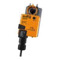
LMB24-SR
95
2 1.5 (0.2)
LMB24-SR.1
95
2 1.5 (0.2)
LMB24-SR-T
95
2 1.5 (0.2)
LMB24-SR-T.1
95
2 1.5 (0.2)
LMB24-3-P5-T
95
2 1.5 (0.2)
LMX24-SR
95
2 1.5 (0.2)
LMX24-SR-T
95
2 1.5 (0.2)
LMX120-SR
95
4 2 (0.5)

 Loading...