800-543-9038 USA 866-805-7089 CANADA 203-791-8396 LATIN AMERICA
Accessories
-
2
3/4” [20 mm] Shaft Clamp
V6-2
Shaft Extensio
G-LMS
Shaft Adaptor for 1/2” Diameter Shafts
-LM
A-1 Shaft Adaptor for 3/8” Diameter Shafts
-T Terminal
over for NEMA 2
-1
W
th
r
hi
l
-
t
l
-1
Weather Shield - Pol
carbonate
oo
-0
8 mm
10 mm
renc
S1A, S2
Auxiliary Switch(es
370
haft Mount Auxiliary
witch
P…A Feedback Potentiometer
A2
Min positioners in NEMA 4 housin
SGF24 Min positioners for flush panel mountin
PTA-2
P
l
Wi
th M
l
ti
n Int
rf
IRM-10
Input Rescaling Module
D
-100 Analo
to Di
ital
witch
G-R01 Resistor for 4 to 20 mA Conversion
NSV24 US Battery Back-Up Module
G-X40 Trans
orme
N
TE
When usin
LMB
X
24-SR… actuators, only use accessories listed on this pa
e.
Typical Specification
roportional control damper actuators shall be electronic direct-coupled type,
which require no crank arm and linka
e and be capable o
direct mountin
to a
shaft from 1/4” to 5/8”. Shafts u
to 3/4” diameter can be accommodate with an
accessory clamp. Actuators must provide proportional damper control in response
to a 2 to 10 VD
or, with the addition of a 500
res
stor, a 4 to 20 m
contro
nput
from an electronic controller or positioner. Actuators shall have brushless DC motor
technolo
y and be protected from overload at all an
les of rotation. Actuators shall
have reversin
switch and manual override on the cover. I
required, actuator will be
provided with screw terminal strip for electrical connections
LMB24-SR-T
. Run time
shall be constant and independent of torque. A 2 to 10 VD
feedback signal shall be
provided
or position indication. Actuators shall be cULus listed, have a 5-year war-
rant
, and be manufactured under ISO 9001 International Qualit
Control Standards.
ctuators shall be as manufactured b
Belimo
LMB
X
24-
R
-T
Proportional, Non-Sprin
Return, 24 V, for 2 to 10 VDC or 4 to 20 mA
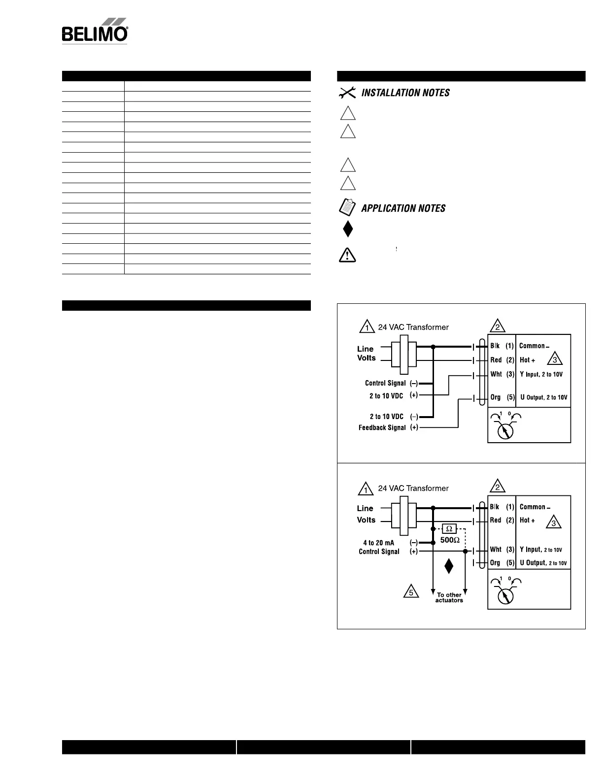
Wiring Diagrams
1
rovide overload protection and disconnect as required
2
AUTIO
quipment Damage
Actuators may be connected in parallel.
ower consumption and input impedance must be observed.
Actuators may also be powered by 24 VDC.
nly connect common to ne
.
–
le
of control circuits
The ZG-R01 500
resistor converts the 4 to 20 mA control signal t
2 to 10 VDC, u
to 2 actuators ma
be connected in
arallel
Live Electrical Components!
During installation, testing, servicing and troubleshooting of this product, it may be
ecessary to work with live electrical components. Have a quali
ed licensed electrician or other
ndividual who has been properly trained in handlin
live electrical components per
orm these
tasks. Failure to
ollow all electrical sa
et
recautions when ex
osed to live electrical com
o-
ents cou
resu
t
n
eat
or ser
ous
n
ury
W565
0
2 t
1
VD
ntr
l
W565
08
t
2
m
ntr
M40024 - 05/10 - Sub
ect to chan
e. © Belimo Aircontrols
USA
, Inc.
 Loading...