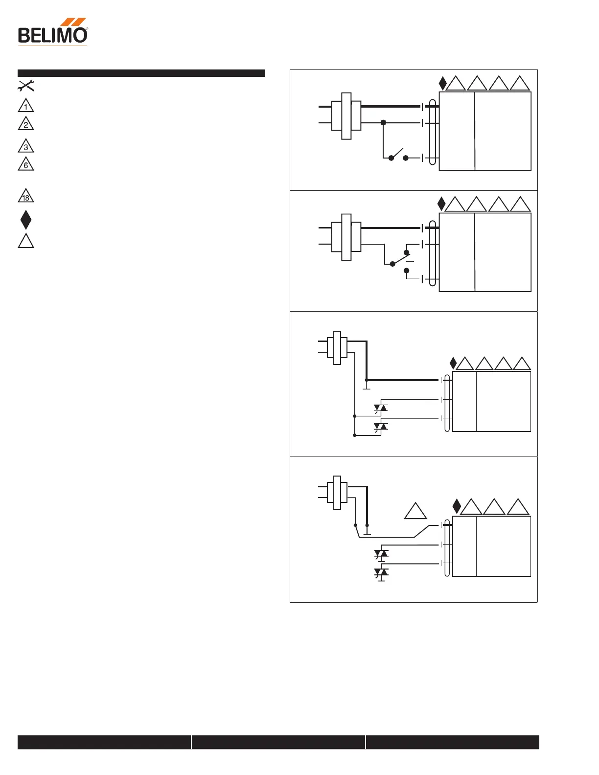
Wiring Diagrams
INSTALLATION NOTES
Provide overload protection and disconnect as required.
Actuators may be connected in parallel. Power consumption and input
impedance must be observed.
Actuators may also be powered by 24 VDC.
Actuators Hot wire must be connected to the control board common.
Only connect common to neg. (-) leg of control circuits. Terminal
models (-T) have no-feedback.
Actuators with plenum cable do not have numbers; use color codes
instead.
Meets cULus requirements without the need of an electrical ground
connection.
!
WARNING! LIVE ELECTRICAL COMPONENTS!
During installation, testing, servicing and troubleshooting of this
product, it may be necessary to work with live electrical components.
Have a qualified licensed electrician or other individual who has been
properly trained in handling live electrical components perform these
tasks. Failure to follow all electrical safety precautions when exposed to
live electrical components could result in death or serious injury.
2 3 18
24 VAC Transformer
Blk (1) Common
Red (2) + Hot
Wht (3) Y Input
olts
1
On/Off
2 3 18
24 VAC Transformer
Blk (1) Common
Red (2) + Hot
Wht (3) Y Input
olts
1
Floating Point
ComHot
2 3 18
Blk (1) Common
Red (2) + Hot
Wht (3) Y Input
olts
1
2
18
Blk (1) Common
Red (2) + Hot
Wht (3) Y Input
olts
ComHot
6
1
Floating Point - Triac Sink
LRB24-3
On/Off, Floating Point, Non-Spring Return, 24 V
800-543-9038 USA 866-805-7089 CANADA 203-791-8396 LATIN AMERICA / CARIBBEAN
Date created, 11/29/2017 - Subject to change. © Belimo Aircontrols (USA), Inc.