5
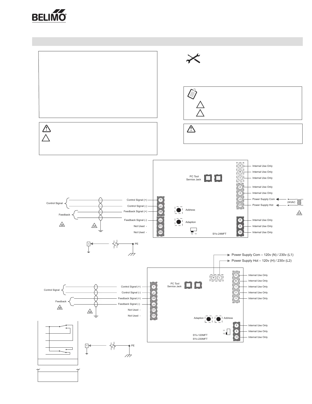
Wiring
Proportional, 24V, 120/230V
W547-2
Actuators: SY4...5-24MFT SY4...12-120MFT SY4...12-230MFT
Each actuator should be powered by a single, isolated
control transformer.
• Power supply Com/Neutral and Control Signal "–" wiring to a common is
prohibited.
Actuator: SY2…5-24MFT SY2...12-120MFT SY2...12-230MFT
Observe Class 1 and Class 2 wiring restrictions.
Transformer sizing = SY actuator draw X 1.25 (safety margin)
(Ex. SY2-24 requires 3.0A x 1.25 = 3.75A, 3.75A X 24 VAC = 90VA Transformer)
Indicates an action or condition that may cause irreversible
damage to the actuator(s) or associated equipment.
Equipment damage!
Power consumption and input impedance must be observed.
CAUTION
Indicates a potentially hazardous situation which, if not avoided,
may result in minor or moderate injury. It may also be used to
alert against unsafe practices.
Warnings and Cautions appear at appropriate sections throughout
this manual. Read these carefully.
Hazard Identification
33
INSTALLATION NOTES
Use of feedback is optional.
APPLICATION NOTES
34
36
Ground shielded wire at control panel chassis.
Tape back ground at actuator.
NOTES SY2...5-24MFT
NOTES SY2...12-120MFT (230MFT)
• Caution: Power supply voltage.
SY2...5-24MFT
SY2...12-120MFT
(230MFT)
A
B
C
E
F
Contact Rating: 5A 125 VAC Max.
3A 250 VAC Max.
A-B (Open Indication)
LS4
LS3
A-E (Closed Indication)
Power Supply Com – 120v (N) / 230v (L1)
Power Supply Hot – 120v (H) / 230v (L2)
SY4...5-24MFT
SY4...12-120 (230MFT)
SY4...5-24MFT
SY4...12-120
(230MFT)
71906-00001 Subject to change. © Belimo Aircontrols (USA), Inc.
 Loading...