I20683 - Subject to change.
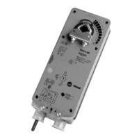
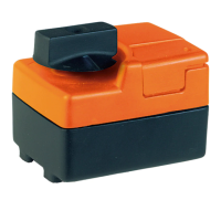
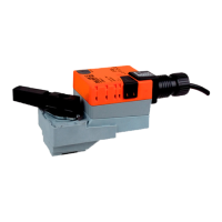
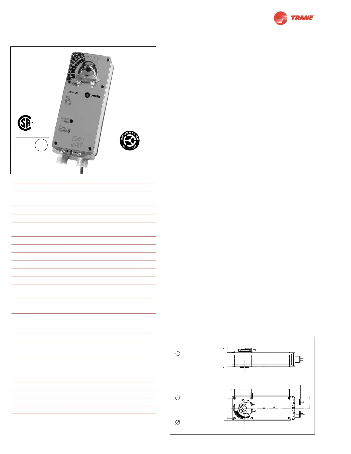
TNF24-SR
Proportional Damper Actuator, Spring Return Fail-Safe, 24 V for 2 to 10 VDC, or 4 to 20 mA Control Signal.
Output Signal of 2 to 10 VDC for Position Indication
Torque min. 60 in-lb, for control of air dampers
Application
For proportional modulation of dampers in HVAC systems.
Actuator sizing should be done in accordance with the damper
manufacturer’s specifications.
The actuator is mounted directly to a damper shaft up to 1.05”
in diameter by means of its universal clamp. A crank arm and
several mounting brackets are available for applications where
the actuator cannot be direct coupled to the damper shaft.
The actuator operates in response to a 2 to 10 VDC, or with the
addition of a 500Ω resistor, a 4 to 20 mA control input from an
electronic controller or positioner. A 2 to 10 VDC feedback signal
is provided for position indication or master-slave applications.
Operation
The TNF series actuators provide true spring return operation
for reliable fail-safe application and positive close-off on air tight
dampers. The spring return system provides constant torque to
the damper with, and without, power applied to the actuator.
The TNF series provides 95° of rotation and is provided with a
graduated position indicator showing 0° to 95°.
The TNF24-SR uses a brushless DC motor which is
controlled by an Application Specific Integrated Circuit (ASIC)
and a microprocessor. The microprocessor provides the
intelligence to the ASIC to provide a constant rotation rate and
to know the actuator’s exact fail-safe position. The ASIC
monitors and controls the brushless DC motor’s rotation and
provides a digital rotation sensing function to prevent damage
to the actuator in a stall condition. The actuator may be stalled
anywhere in its normal rotation without the need of
mechanical end switches.
For all accessories, see pages 110 and 132.
Technical Data TNF24-SR
Power supply 24 VAC ± 20% 50/60 Hz
24 VDC ± 10%
Power consumption running: 3 W; holding: 1 W
Transformer sizing 6 VA (class 2 power source)
Electrical connection 3 ft, 18 GA appliance cable
1/2” conduit connector
Overload protection Electronic throughout 0° to 95° rotation
Operating range Y 2 to 10 VDC, 4 to 20mA
Input impedance 100 kΩ (0.1 mA), 500Ω
Feedback output U 2 to 10 VDC (max. 0.5 mA) for 95°
Angle of rotation 95°, adjustable 30° to 95° w/accessory
Torque 60 in-lb [7 Nm] constant torque
Direction of rotation spring: reversible with cw/ccw mounting
motor: reversible with built-in switch
Position indication visual indicator, 0° to 95°
(0° is spring return position)
Running time motor: 150 sec constant,
independent of load
spring: < 60 sec
Humidity 5 to 95% RH non-condensing
Ambient temperature -22°F to +122°F [-30°C to +50°C]
Storage temperature -40°F to +176°F [-40°C to +80°C]
Housing NEMA type 2 / IP54
Housing material zinc coated metal
Agency listings UL 873 listed, CSA C22.2 No.24 certified
Noise level max. 45 dB (A)
Servicing maintenance free
Quality standard ISO 9001
Weight 6.0 lbs (2.7 kg.)
 Loading...