50
I20683 - Subject to change.
Preliminary Steps
1. Actuators should be mounted indoors in dry, relatively
clean environment free from corrosive fumes. If the actua-
tor is to be mounted outdoors, a protective enclosure must
be used to shield the actuator.
2. For new construction work, order dampers with extended
shafts. Instruct the installing contractor to allow space for
mounting and service of the actuator on the shaft.
3. For standard mounting, the damper shaft must extend at least
3 1/2" from the duct. If the shaft extends less than 3 1/2", the
actuator may be mounted in its short shaft configuration. If an
obstruction blocks access, the shaft can be extended with the
AV 10-18 shaft extension
(K6-1 is required).
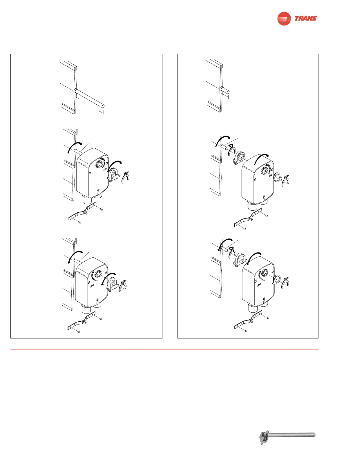
Installation Instructions
Quick-Mount Visual Instructions
1. Rotate the damper to its failsafe position. If the shaft rotates
counterclockwise, mount the “CCW” side of the actuator out. If it
rotates clockwise, mount the actuator with the “CW” side out.
2. If the universal clamp is not on the correct side of the
actuator, move it to the correct side.
3. Slide the actuator onto the shaft and tighten the nuts on the
V-bolt with a 10 mm wrench to 6-8 ft-lb of torque.
4. Slide the anti-rotation strap under the actuator so that it
engages the slot at the base of the actuator. Secure the
strap to the duct work with #8 self-tapping screws.
NOTE: Read the “Standard Mounting” instructions, on the next
page, for more detailed information.
Standard
Mounting
Short Shaft
Mounting
Dimensions
[All numbers in brackets are in millimeters.]
Quick-Mount Visual Instructions
 Loading...