52
I20683 - Subject to change.
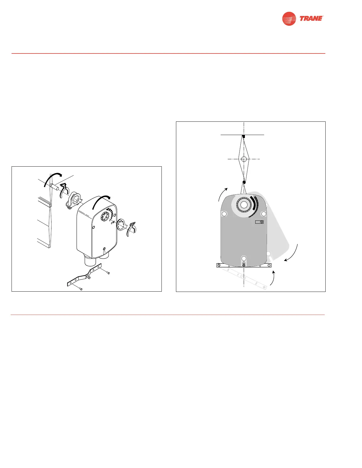
If the shaft extends at least 3/4” from the duct, follow these
steps:
1. See Figure D. Move damper blades to the fail-safe position (a).
2. Determine the best orientation for the universal clamp on the
back of the actuator. The best location would be where you
have the easiest access to the V bolt nuts on the clamp.
3. Engage the clamp to the actuator as close as possible to
the determined location.
4. Lock the clamp to the actuator using the retainer clip.
5. Mount the spring return actuator to the shaft. Tighten the
universal clamp, finger tight only.
6. Mount the anti-rotation strap at the base of the actuator. Do
not tighten the screws.
7. Remove the screw from one end of the mounting bracket
and pivot it away from the actuator.
8. Loosen the universal clamp and, making sure not to move
the damper shaft, rotate the actuator approximately 5° in
the direction which would open the damper.
9. Verify that the damper is still in its full fail-safe position.
10. Tighten the universal clamp to the shaft.
11. Rotate the actuator to apply pressure to the damper seals
(b) and re-engage the anti-rotation strap (c).
12. Tighten all fasteners.
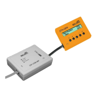
13. Use IND-LF accessory if position indication is needed.
Installation Instructions
Short Shaft Mounting with IND-LF Position Indicator / Airtight Damper Procedure
Initialization of the TLF24-SR
When power is applied, the internal microprocessor
recognizes that the actuator is at its full fail-safe position and
uses this position as the base for all of its position calcula-
tions. This procedure takes approximately 15 seconds. During
this time you will see no response at the actuator. The micro-
processor will retain the initialized zero during short power fail-
ures of up to 25 seconds. When power is applied during this
period, the actuator will return to normal operation and pro-
ceed to the position corresponding to the input signal provid-
ed. For power failures over 25 seconds, the actuator will be at
it fail-safe position and will go through the start up initialization
again.
Motor Position Detection
A Brushless DC motors eliminate the need for potentiometers
for positioning. Inside the motor are three “Hall Effect” sen-
sors. These sensors detect the spinning rotor and send pulses
to the microprocessor which counts the pulses and calculates
the position to within 1/3 of a revolution of the motor.
Overload Protection
The TLF, on-off actuators are electronically protected against
overload. The TLF, On-off actuators have an internal current
limiter which maintains the current at a safe level which will not
damage the actuator while providing adequate holding torque.
The TLF24, modulating actuators (TLF24-SR, TLF24-3) are
protected against overload by digital technology located in the
ASIC. The ASIC circuitry constantly monitors the rotation of the
brushless DC motor inside the actuator and stops the
pulsing to the motor when it senses a stall condition. The motor
remains energized and produces full rated torque during stall
conditions. The actuator will try to move in the direction of the
stall every 2 minutes, for a period of 32 minutes. After this, the
actuator will try again every 2 hours.
Operational Information for TLF24-SR Actuators
 Loading...