54
I20683 - Subject to change.
Installation Instructions
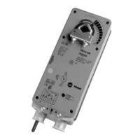
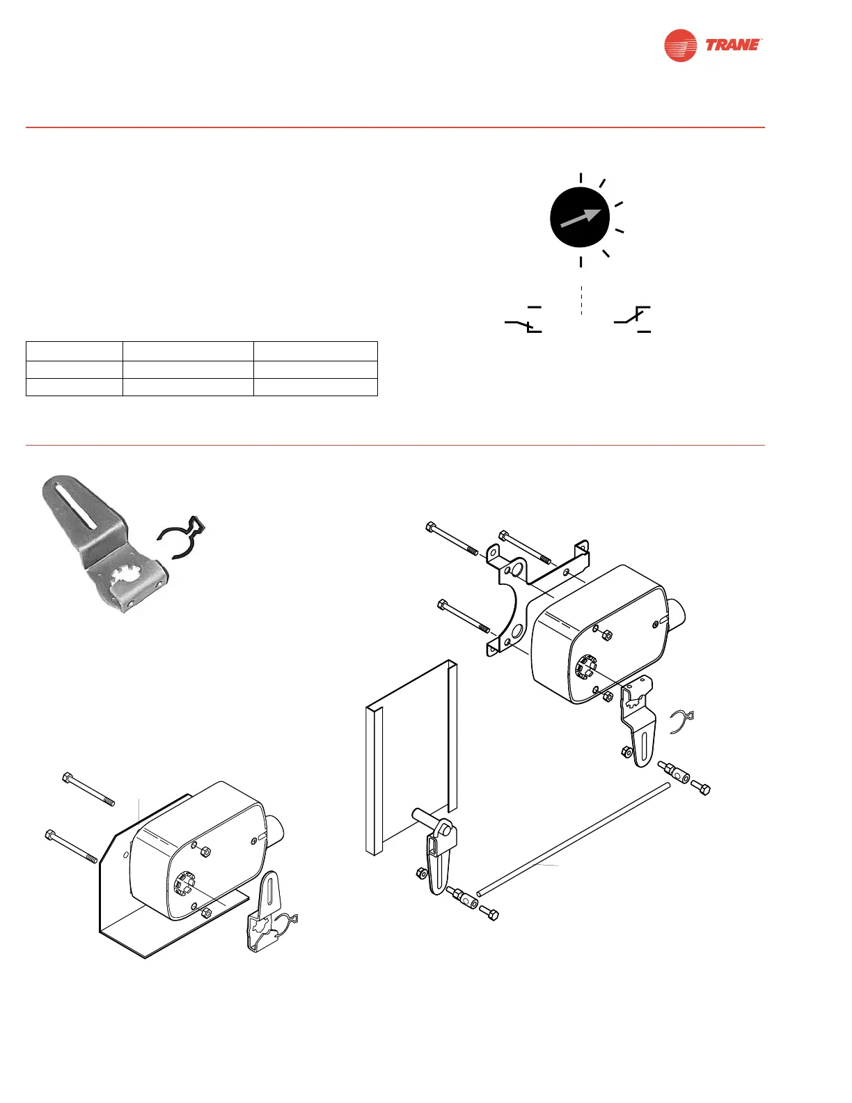
The …-S model actuators are equipped with an adjustable
auxiliary switch used to indicate damper position or to
interface additional controls or equipment. Switching positions
can be set over the full 0 to 95° rotation simply by setting a
switch on the actuator.
1. Set desired switch position (Example 60%).
2. As the actuator rotates, the switch indicator moves from .6
(60%) toward 0 (0%). When the indicator passes 0 the
switch contact between S1 and S2 is broken and the con-
tact between S1 and S3 is made.
Auxiliary Switches
Non-Direct Mounting Methods
KH-LF Crankarm including retaining ring
KH-LF
For shafts up to 1/2”
ZG-112
(pushrod not supplied with kit)
KG6 ball joint and
universal crankarm
(not included)
KG6 ball joint
(not included)
KH-LF
crankarm
KH-LF
crankarm
ZG-LF2
Crankarm Adaptor Kit
ZG-LF112
Crankarm Adaptor Kit
Voltage Resistive load Inductive load
120 VAC 6 A 3 A
250 VAC 6 A 1.5 A
Switch Rating
 Loading...