9
I20683 - Subject to change.
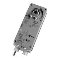
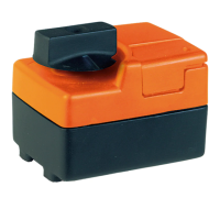
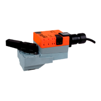
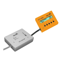
Spring Return Actuator Product Range
Actuator Application Chart
TAF24 ● 150 <20 ● 10 5 (1.5) ● 14
TAF24-S ● 150 <20 ● 10 5 (1.5) ●●14
TAF24-SR ● 150 <20 ● 10 6 (2) ●● 16
TNF24 ● <75 <60 ● 8 5 (2.6) ● 30
TNF24-S ● <75 <60 ● 8 5 (2.6) ●●30
TNF24-SR ● 150 <60 ● 6 3 (1) ●● 32
TLF24 ● < 40 to 75 <25
♦
● 7 5 (2.5) ● 44
TLF24-S ● < 40 to 75 <25
♦
● 7 5 (2.5) ●●44
TLF24-SR ● 150 <25
♦
● 5 2.5 (1) ●● 48
TLF24-3 ● 150 <25
♦
● 5 2.5 (1) ● 46
TTF24 ● < 75 <25
♦
● 4 2 (1.3) ● 60
TTF24-S ● < 75 <25
♦
● 4 2 (1.3) ●●60
TTF24-SR ● 95 <25
♦
● 3 2 (1) ● 64
TTF24-3
● 95 <25
♦
● 5 2.5 (1) ● 62
♦
<60 seconds @-22°F [-30°C]
For complete guide to sizing actuators see page 5.
18 in-lb [2 Nm], Apprx. 4.5 sq. ft.
35 in-lb [4 Nm], Apprx. 8 sq. ft.
60 in-lb [7 Nm], Apprx. 15 sq. ft.
133 in-lb [15 Nm], Apprx. 33 sq. ft.
Motor Drive
Spring Return
24 VAC +/- 20%, VDC +/- 15%
VA rating
Wattage running (holding)
On/Off
Floating Point
2-10 VDC (Default)
4-20 mA* (w/500 ohm resistor)
2-10 VDC (Default)
1 SPDT, 3A (0.5A inductive) @250 V
1 SPDT, 6A (1.5A inductive) @250 V
2 SPDT, 7A (2.5A inductive) @250 V
See Page Number
Running Power Power Control Position Auxiliary
Time Supply Consumption Input Feedback Switches
Torque
(based on 4 in-
lb per sq. ft)
Spring Return
Airside Products
B
B