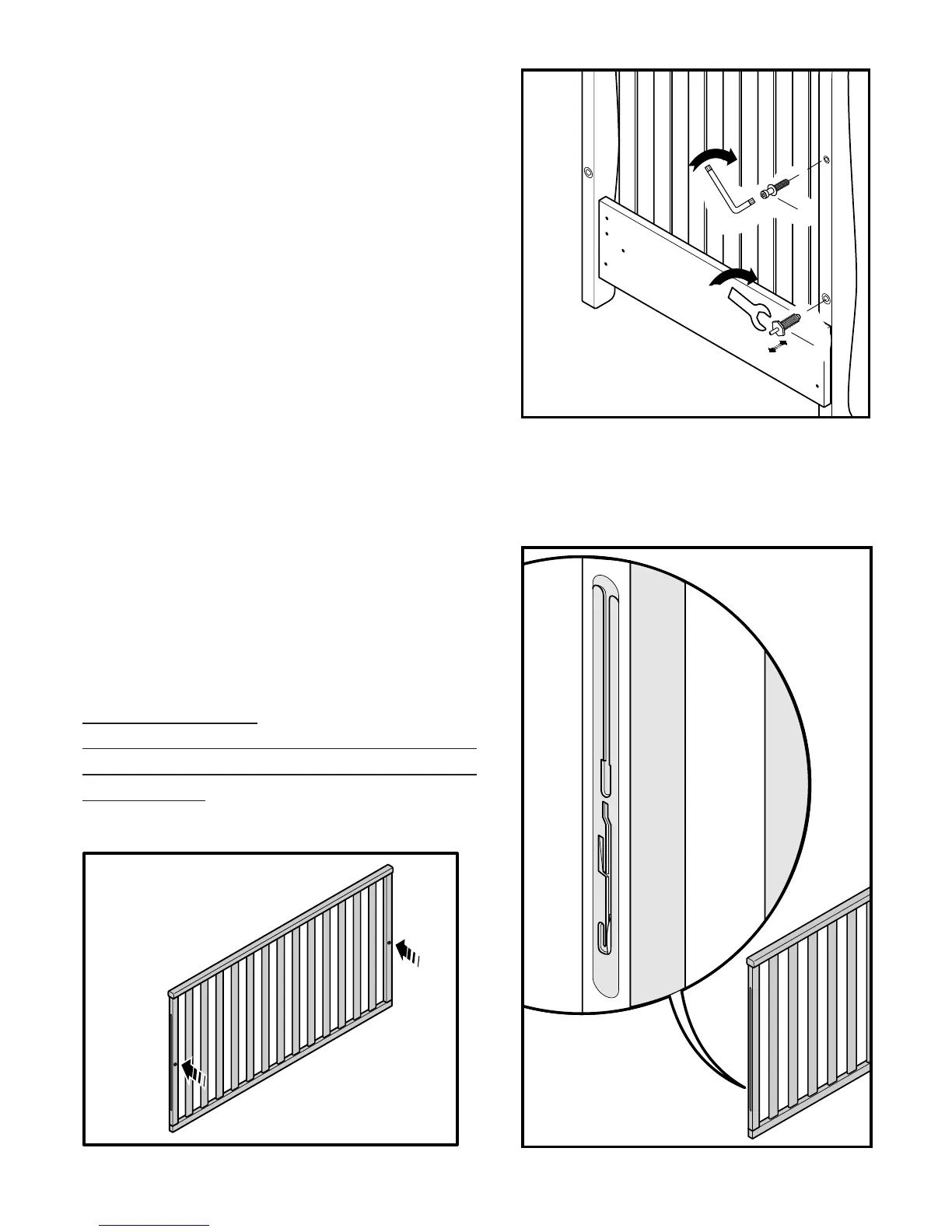
STEP 6 Diagram 5
Insert screw “X” into the upper hole in the head-
board and tighten fully using wrench “B”.
Proceed in the same way to insert screw “Y” into
the lower hole using spanner “Y
2”.
Diagram 6
Detail of the dropside mechanism.
IMPORTANT:
THE DROPSIDE MUST BE FITTED WITH THE
REFERENCE MARKS FACING THE INTERIOR
OF THE CRIB.