Pure sine wave
Performance introduction
An inverter is a power supply that conver ts direct current (batteries, solar cells, wind turbines, etc.)
into alternating current. Because of the high frequency inverter used in power conversion
technology, ferrite transformer to replace the old bulky silicon steel transformer. This is why the
inverter of our company is lighter weight and less bulky than other inverters that have similar rated
power. When the inver ter works in the inverter mode, the output waveform is modified sine wave. It
is a practical wave which waveform characteristic is similar to pure sine wave. This waveform is most
suitable for linear load and switching power supply of electronic equipment, such as light bulbs, rice
cookers, energy saving lamps, etc.. It can also be applied to inductive loads, such as transformers,
motors, etc.
The correct value of the modified sine wave for inverter output is 220V, which is the same as the
standard home power supply. Most AC voltmeters (digital and analog) use sensitive averaged
waveforms instead of RMS values.
Their calibration is set at RMS
voltage, which is used to measure
pure waves. Using them to
measure the output voltage of
the inverter, it is possible to
detect a low voltage 20V-30V. In
order to measure accurately,
please use the voltmeter which
can measure the effective value.
Using environment
In order to achieve the best use effect, please put the inverter in the surface of the smooth place,
such as the ground, the floor of the car, or other solid surface. Let the inverter power line can be
fixed easily. The working place should meet the following standards:
1.Do not allow the inverter to contact with water or other liquid to keep the inverter away from
moisture or water.
2.In a cool environment, the temperature is 0 degrees (without condensation) to 40 degrees. Don't
put the inverter next to the heating vents or other heating devices. Keep the inver ter out of the
sun as much as possible.
3.Keeping the ventilation and the absence of obstructions around it ensures that air is free to
circulate. When the inverter is working, do not put something on the inverter. The inverter fan is
used to help dissipate the heat.
4.Be careful not to use inverters near flammable materials or places where flammable gases can be
gathered.
5.The batter y not only provides a dc voltage of 11V to 15V, but also provides sufficient current to
run the load. The power supply should be a good battery full of electricity. To estimate roughly
the current required for a load, it can be estimated by dividing the power of the load by 10.
Continuous frequently open and close inverters can cause damage.
Non-professional technicians, do not open inverter shell
Rated current and actual use of equipment
The nominal current or power of most power tools, household appliances and video and audio
equipment is much smaller than the nominal power range of the inverter, but overload protection
occurs when they are started. Inverter is the most easy to drive resistive load or switching power
supply load. Because the resistive load is a linear load, it can work full load. Such as electric stove,
rice cooker, LCD TV and other equipment.
Some audio-visual equipment and electric tools to a greater level than resistive load power can
work normally, such as asynchronous motor, CRT TV, compressor, water pump etc. 2 to 6 times the
working current is required to start. The ability to run specific loads is subject to test.
Warming
Warming
Normally the fuse will not burn out unless serious circuit failure occurs.
When the inverter fails, please do not try to repair it yourself. Please
contact a professional technician to deal with the machine, there will be
high voltage electric shock hazard.
Common problem
Electric tools and microwave ovens cannot start
Carefully read the information on each power tool and accurately determine the input
power of the tool. Whether the output power is enough to run the tools and microwave
ovens, remember that power tools may need 2 to 6 times power requirements.
Television interference
The inverter has little interference with the television signal. However, in some cases,
some disturbances are still visible, especially when the television signal is weak.
Please try the following methods:
1.Try to keep the inverter away from the TV antenna or lengthen the TV antenna cable;
2. Adjust the direction of the inverter.
3.Ensure that the antenna provides strong signal strength to the TV set, and use high
quality antenna cable with good shielding effect.
4.When you watch TV, do not run high power electrical equipment or tools.
5.There is no way to completely disappear some of the old TV interference.
1.Wiring diagram is only for basic reference, please contact professional technical
personnel for actual installation.
One or more batteries can be used in inverters. One or more batteries can be used in
inverters. It's better to use 150AH or batteries with bigger capacity.
2.Since it may be necessary to connect the batter y for these operations, make sure there is no
flammable gas around before connecting.
Connect the inverter and the battery with the cables supplied with the inverter (excluding the
high-power mode cable). The red cable is connected to the red terminal of the inver ter input
terminal and the positive terminal of the batter y. The black cable is connected to the inverter Input
terminal black and battery negative. Please ensure that all cables are stable and reliable.Improper
connection may result in overheating of the cable, damage to terminals and lugs. At the same time
will cut down the batter y power supply time. Turn the inverter mode to ON, if your battery is fully
charged, the light of inverter will display green. The inverter is protected if the light displays red,
so tr y to solve it before using.(Check whether the battery voltage is too high or too low, the
inverter output is overload or short circuit)。
The power source for the 12V inverter can be used with a 12V battery or several 12V batteries in
parallel to increase the battery's power supply time.
3.Inverter must be connected to the same nominal voltage of the batter y, 12V inverter
connected to the 12V battery, 24V inverter connected to the 24V batter y
4.Before you plug in all your power devices, make sure all devices are shut down.
Turn on the inverter mode switch, the POWER on the edge of the LED emits green light, and then
you can open your device one by one, if your device is not overloaded, now can work properly. If
LED glows red, it's overloaded .You need to reduce load restart to work.
Refer to the above connection diagram
1.First turn off the power switch of the inverter.
2.U se a black DC cable to connect the negative terminal of the battery
to the black terminal of the inverter.
3.C onnect the positive terminal of the battery to the red terminal of the
inverter with a red DC cable.
4.Plug the power supply plug of the power equipment into the output
socket of the inverter.
5.O pen the inverter power switch can be used.
Disassembly steps:
1. First turn off the power switch of the inverter;
2.Pull out the power plug of the load.
3.R emove the red DC cable;
4.Remove the black DC cable
For example, when the power of an AC load is 100W, the current
supplied by the power supply must be 100/10=10A. In the need of a
larger current, you can use several batteries in parallel to use. The most
important thing is to ensure that there is enough cross-sectional area
of the connecting cable. This manual does not list all battery pack
types. The battery's charging and battery configuration belong to
another professional categor y.
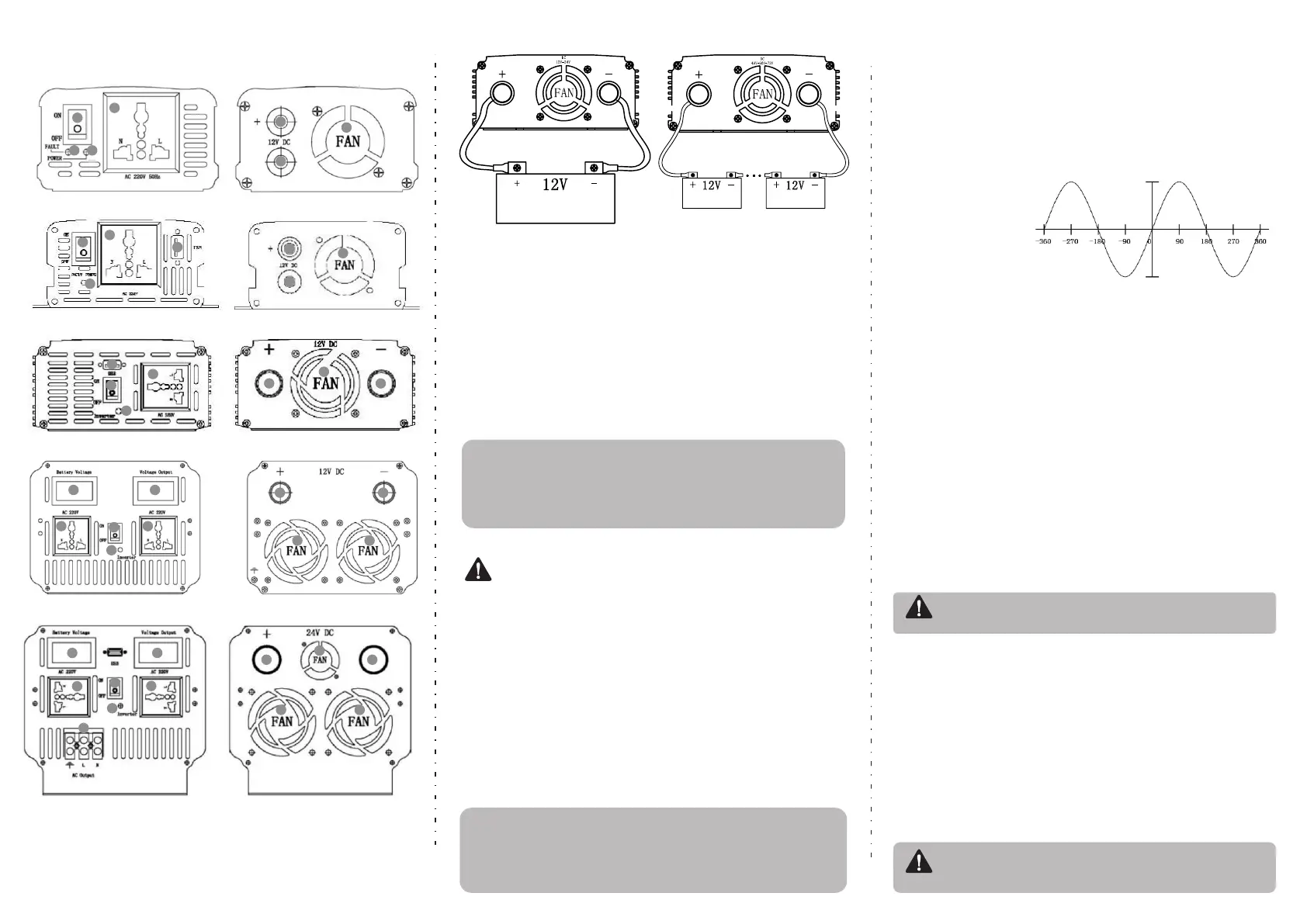
24V-36V-48V-72V
Connection diagram
12V Connection diagram
1、Power switch
2、AC output socket
3、Power indicator
4、Status indicator
5、USB Interface
6、Positive(red)
Pure sine wave inverter front and rear panel diagram
BEP150S Panel diagram
BEP300A/500SA Panel diagram
BEP1000S Panel diagram
BEP800S/1500S/2000S/3000S Panel diagram
BEP5000S Panel diagram
The product panel is for reference only.Please refer to the actual product.
Install the connection step:
●.In the installation of connecting cables should use a suitable cable, such as 220V output
cable is too long or the wire cross-sectional area is too small, there will be a lot of power
loss in the cable, the load side of the performance of small power, low voltage.
●.Batteries and inverter connection cable is not standardized, the cable is too long, the
cross-sectional area is too small, bad connection parts, will cause a lot of power loss.
Performance for the lack of output power, the battery voltage is too low, short working
hours, and even turn on the alarm does not work. At the same time the cable should be
waterproof, dielectric strength must meet the requirements of the use of the environment.
Installation method
12V Connection diagram
Battery
24V-36V-48V-72V
Connection diagram
Battery
Battery
1
1
1
1
1
2
2
2
2
2
2
2
3
4
6
6
6
6
6
7
7
7
7
7
8
8
8
8
8
8
8
8
11
11
11
11
5
5
9
10
9
10
12
7、Negative(black)
8、Cooling fan
9、Voltage input monitor
10、Voltage output monitor
11、Double color status indicator
12、AC output interface
Warming
 Loading...