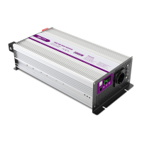
Pure sine wave inverter
CATALOGUE
User Manual
1. Safety Cautions --------------------------------------------------------------------------
1
2. Product introduction--------------------------------------------------------------------- 1
2.1 Features ----------------------------------------------------------------------------- 1
2.2 Main Specifications --------------------------------------------------------------- 2
3. Panel description -----------------------------------------------------------------------
2
3.1 Front Panel Description ---------------------------------------------------------
2
3.2 Front Panel Diagram ------------------------------------------------------------- 3
3.3 Indications of LED signals of the front panel ------------------------------- 3
3.4 Rear Panel Description ---------------------------------------------------------- 3
4. Settings of lnitial Output Voltage,Frequency,Standby Sacing Mode ------- 3
4.1 lnstruction of lnitial Factory Setting -------------------------------------------
3
5. Protection Functions ------------------------------------------------------------------- 4
5.1 lnput Protection -------------------------------------------------------------------- 4
5.2 Output Protection ----------------------------------------------------------------- 4
5.3 lnstruction of Fault Signal ------------------------------------------------------- 4
6. lnstallation and Wiring ----------------------------------------------------------------- 5
6.1 Battery Wire ------------------------------------------------------------------------ 5
6.2 Battery Pack Recommendation ----------------------------------------------- 5
6.3 lnstallation Requirements ------------------------------------------------------- 6
6.4 Fixing Recommendation -------------------------------------------------------- 6
6.5 Reference Diagram of Setup -------------------------------------------------- 7
7. Troubleshooting -------------------------------------------------------------------------- 7
8. Cautions for the Electrical Load ----------------------------------------------------- 7
9. Warranty ----------------------------------------------------------------------------------- 7
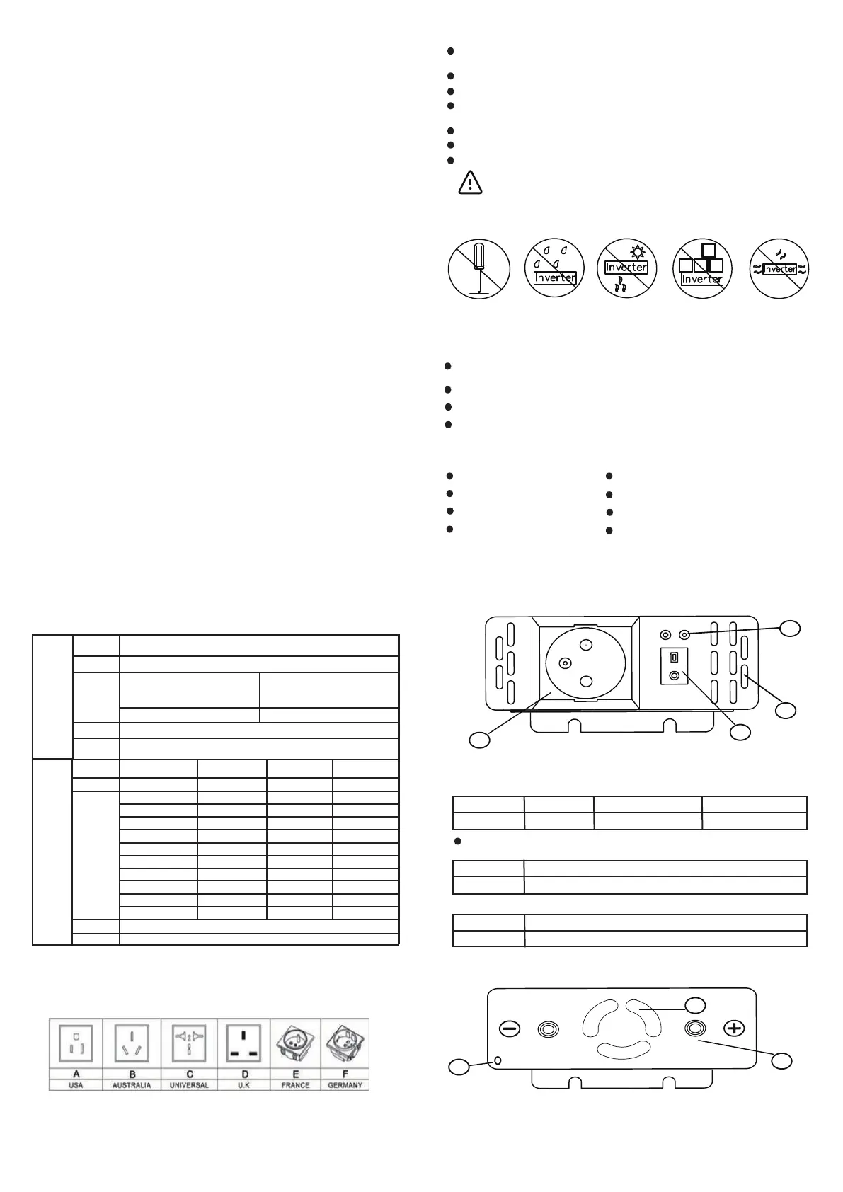
3.2Front Panel Diagram
3.3 Indications of LED signals of the front panel
Status LED (Status LED): that is in the work mode
LED Display
State mode
GREEN
Normal
ORANGE
Standby Saving Mode
RED
Abnormal/Protection
When display abnormal,please refer to the instruction 5.2,5.3 or 7.of the manual to troublesh
Battery LED:Display the remaining capacity of the external batteries.
LED Display
STATE MODEL
Indication of 4 red LEDs
Battery =25%-50%-75%-100%
LOAD LED: Display the current capacity
LED Display
STATE MODEL
Indication of 4 red LEDs
Battery =25%-50%-75%-100%
3.4 Rear Panel Description
(1)Battery input Terminals(+)(-) (2)Air Vents(Fan) (3)Earth terminal of the chassis(FG)
4. Settings of Initial Output Voltage, Frequency,Standby Saving Mode
4.1 Instruction of Initial Factory Setting
(1)Factory Setting is 220Vac/50Hz or 110Vac/60Hz
(2)Set the Standby Saving Mode enabled(Not in use)
-3-
1
2
3
4
Fault
Power
ON
OFF
FAN
1
2
3
1. Safety Precautions (Please read this manual carefully before installing)
The machine contains high voltage with a potential hazard, if abnormal must be handled
by qualified technical personnel, do not open the Inverter cover.
Do not place Inverter in a humid environment and near water.
Do not place Inverter in a high-temperature environment, direct sunlight or near fire.
Replace the battery, please use the same brand and the same type of battery equipment,
is strictly prohibited using different brands or different capacity batteries at the same time use.
Do not keep the battery or battery near the fire source, or explode wounding.
Keep the Inverter before or after the air intake or exhaust (please keep at least 15cm or more).
Do not stack other items on the Inverter cabinet.
Warning: The battery will increase with the use of life and aging problems,
once the battery aging, the need for professionals to do the replacement or
treatment, or the battery may be due to leakage and other hazards caused by
the proposed annual maintenance of the battery on a regular basis.
No Disassembling No Humidity No Fire or High
Temperature
Don’t pile
Up Sundries
Keep Ventilation
2. Product Introduction
The off-grid inverter series for the digital CPU control, DC / AC converter,
the use of battery pack to provide energy conversion to AC voltage output.
With a sinusoidal waveform output, long-term work in the 0% -100% load state.
Its instantaneous power of more than 1 times, for inductive, capacitive load and other different load types.
Applications include computers, communications, yachts, SUV, home recreation equipment, motors, power
tools, industrial control equipment, various types of audio and video appliances and other applications.
2.1 Features
Sine wave output (THD <3%)
Highest efficiency output up to 91%
Full LED display working status
Too low battery capacity warning
Full digital control tips
The product complies with CE/FCC/LVD/ROSEspecifications
Can be applied to most AC input products
One-year free product maintenance and warranty
-1-
-2-
No Load
Current Draw
Protection
See the technical specifications
Overcurrent protection, battery reverse protection (built-in fuse) battery is too low warning and power protection
2.2 Main Specifications
40V-60V
91%
8.2A
16A
27A
41A
55A
68A
82A
109A
137A
165A
INPUT
OUTPUT
20V-30V
90%
17A
33A
55A
83A
111A
138A
167A
Factory Setting: 110V AC±3V
Through settings: 110/115/120V AC
60±0.5Hz
Model
Power
Voltage
Frequency
Waveform
Protection
PS300W PS600W PS1000W PS1500W PS2000W PS2500W
PS3000W PS4000W PS5000W PS6000W
0% -100% State (continuous use) - (120% - 150% = 10S) - (≤150% = 2S)
Factory Setting: 220V AC±3V
Through settings: 220/230/240V AC
50±0.5Hz
Rated power input, pure sine wave (THD <3%)
shoet-cireuit ptoteclion,over-load protection,
Battery
Voltage
Efficiency
DC
Current
Machine
Model
10.5V-15V
89%
PS300W
Current
PS600W Current
PS1000W Current
PS1500W Current
PS2000W Current
PS2500W Current
PS3000W Current
PS4000W Current
PS5000W Current
PS6000W Current
32A
64A
107A
161A
214A
268A
321A
428A
535A
642A
222A
277A
333A
3. Panel Description
3.1 Front panel description
⑷ LED lights: Show Inverter working status, battery capacity, the use of load and abnormal
status warning.
⑶ air into the air hole: for Inverter cooling stable work, to maintain a smooth ventilation,
to ensure product life.
⑴POWER ON / OFF switch: switch if the switch in the ON position, then Inverter boot.
⑵ AC Outout output socket: the use of the needs of the region, with a variety of different
forms of socket for users to choose.
super-charge protection,over-temperature protection


 To Next Page
 Loading...