-4-
5.Protection Functions
5.1 Input Protection
⑴ battery polarity reverse polarity protection: When the battery input reverse, Inverter internal or external
fuse will be blown, Inverter should be returned to the original maintenance. (For easy replacement: fuse
external, random with a ready-made fuse such as the user accidentally reverse, please open the FUSE
cover to replace the randomly prepared fuse)
⑵ battery low voltage protection: When the battery voltage is lower than the specification value, Inverter
will automatically turn off the AC output and alarm 3 sound failure light long.
⑶ battery high voltage protection: When the battery voltage is higher than the specification value, Inverter
will automatically turn off the AC output and alarm 4 sound failure light long.
WARNING: When using this series of Inverter, enter the battery pack, the voltage condition is
configured for normal operating voltage(The voltage marked by the specification).
If the configuration voltage is too low (such as 24V models with 12V input), then Inverter
will not boot properly.
If the configuration voltage is too high (such as 24V models with 48V input), then Inverter
will be destructive damage.
5.2 Output Protection
If an abnormality occurs, the unit will display a fault message lamp (see Table 5.3) for troubleshooting reference.
⑴ over-temperature protection (OPT): When Inverter internal temperature is too high (70 degrees), will occur OTP
protection, and alarm 5 sound prompt (continuous alarm) fault LED light long, when the temperature dropped to
60 degrees, automatic recovery normal status.
⑵ AC output abnormal protection: When Inverter AC output voltage is high or low, the need to start the new.
⑶ AC output short circuit protection: When the Inverter output occurs when the short circuit or load surge from
the new start, remove the fault (or fault load) automatic recovery or manual recovery.
⑷ battery voltage abnormal protection: when the battery voltage is too high or too low occurs, if the battery
voltage rises to the safe voltage range Inverter will automatically start from the new.
⑸ Output overload protection (OLP): When the load ≧ 120% and ≦ 145% when the embedded buzzer alarm 10S
continuous after the turn off AC output, panel FAUL indicator flashes (reset inverter switch recovery).
⑹ Output overload protection (OLP): When the load ≧ 145% for 2S off AC output, panel FAUL indicator flashes
(reset inverter switch recovery).
Fault InformationBuzzer
1 beep
2 beep
3 beep
4 beep
5 beep
Continuous beep
Normal Startup:Green LED is on,shows the inverter is normal.
Undervoltage Protection:Red LED is on,
shows the battery voltage is too low or depleted
Undervoltage Warning:The storage battery voltage is running out.
Overvoltage Protection:RED LED is on,
shows the battery voltage is too high.
Inverter overload protection: 10S after closing AC output
(need to reset the inverter switch).
Overheat Protection:RED LED is on,
shows the interior of the inverter is overheat.
5.3 Instruction of Fault Signal
6.3 Installation Requirements
The machine weight should be taken into consideration when fixing the machine, and avoid high
temperature and high pressure environment,in order to guarantee a long service life.
The machine uses the built-in fan to force the air-cooled heat, need to keep the front and rear
ventilation openings, to avoid long-term operation in high temperature environment or overload
conditions to operate, in order to avoid the machine can not provide normal function operation or affect
the service life. (Recommended access to the outlet 15 cm, should not hinder the ventilation of the fault)
6.3 Installation Diagram
Inverter
Air
Air
>15cm
>15cm
As shown in the figure, the body shell design to retain four fixed holes, the user can use the
reserved hole to be fixed. (Recommended horizontal fixed, and pay attention to whether the
ventilated ventilation is smooth)
-6-
6.4 Fixing Recommendation
6. Installation and Wiring
6.1 Battery cable:
wire length should be shortened, the following is not more than 1.5 meters for the principle,
and the choice of wire diameter required according to safety regulations, can carry the
current flow of the wire. Wiring too thin will cause the wire to overheat and even cause the
risk of ignition.Please refer to the following table 6-1 actual wiring, please find the dealer or
the original factory to ensure safety
Form 6-1 Wire Using recommendation
Rated Current
16A-25A
25A-32A
32A-40A
40A-60A
63A-80A
80A-100A
100A-125A
≥125A
2.5
4
6
10
16
25
35
50
AWG
12
10
8
6
4
2
1
0
Wire CSA(m㎡)
Safety Wiring Range
6.2 Battery Pack Recommendation
1. The battery pack is configured with the minimum safe start and full load discharge time.
Users can use this table to select a larger capacity (to meet the discharge time) to meet the
needs of the battery pack.
2. Inverter working time is under load conditions, how to determine the time of a battery work,
where the first description of the battery capacity, the battery is the time (AH) to nominal capacity.
Anshi (AH) means the maximum discharge capacity of the battery within 1 hour, such as a battery
nominal 20AH, which in 1 hour maximum output 20A current. We can use this value to count the
time it takes for a battery to drive a load.
The time that a battery needs to drive a load:
Battery capacity (AH) × battery voltage (V) × 0.8 × 0.9 ÷ load = working hours (hours)
3. Because the battery can not be fully discharged, so 20% can not discharge, because the battery
has a memory function, the electric light, the battery is useless, so the maximum power to multiply 0.8
This is the actual power of the battery can work , In the battery can not put the photoelectric at the
same time the inverter also has the conversion efficiency of the problem, for the quasi-sine in general
efficiency of about 90%, so here selected 0.9, and battery capacity × battery voltage × 0.8 × 0.9, this
is the real inverse The total power that the transformer can do to the load.
The battery by the inverter to work on the load time:
For example:a 12V/60Ah Battery, a 220v/100w filament lamp
Working Time=12(V)×60(AH)×0.8×0.9÷100(W)=5.18(Hour)
Explanation:12V--Battery Voltage
60AH--Battery Vapacity
0.8--Battery Capacity
0.9--Inverter Convert Efficierncy
-5-
100(W)--The nominal power the bulb
5.18(Hour)--The working time that a 60AH battery works by the power supply of batteries ps,
there are some errors of the actual discharge time base on the conditions,lifetime,maintenance of batteries.
Solution: battery capacity (AH) × battery voltage (V) = battery can output the maximum power (W)
Working hours = battery capacity (AH) × battery voltage (V) × 0.8 × 0.9 ÷ load
-7-
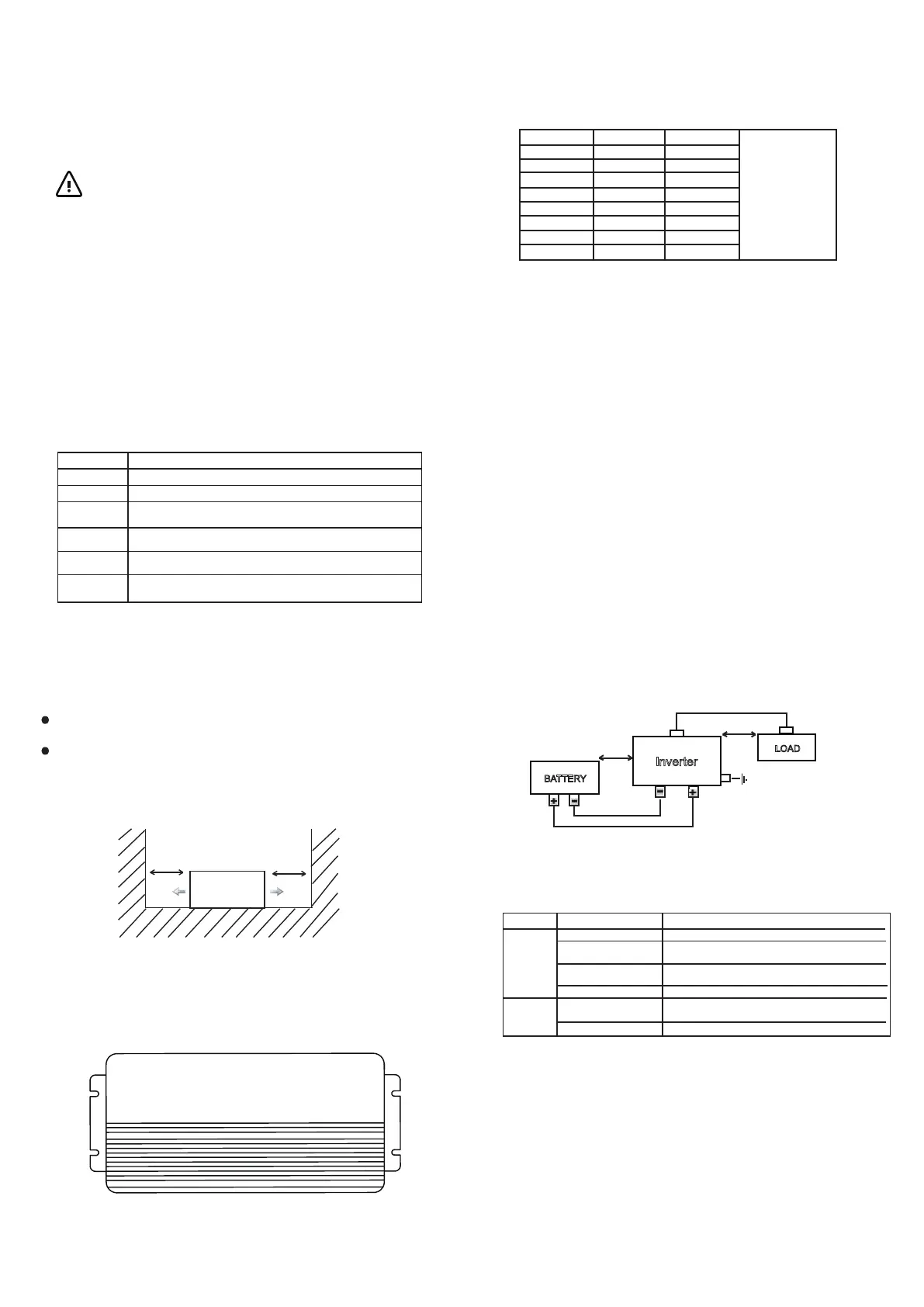
6.5 Rerence Diagram of Setup
BATTERY
Inverter
LOAD
about 15cm
15
about 15cm
15
a 1.5 meter-long wire is recommended
wall or system FG
7. Troubleshooting
This series of inverter power supply for professional goods, due to improper use or modification, can
cause damage or electric shock hazard. Therefore, the company recommends that users according to
the following table after the basic inspection can not return to normal, please contact the dealer or return
to the original maintenance.
Fault state May cause the cause Suggest the method of lifting
AC
voltage
no output
DC voltage abnormality Check if the DC voltage (battery voltage) is too low or too high
Over temperature protection
Check if the radiator vents are open or the temperature is too
high. Please use or lower the ambient temperature
Overload protection
Check whether the load exceeds the rating or requires
large starting current,such as inductive or capacitive devices.
Short circuit protection
Check whether the load exceeds the rating or short-circuited
battery is used for too
long or malfunctioning
Replace battery
battery capacity is too small Confirm specifications recommend increasing battery capacity
Battery
discharge
Time is too
shortrt
8.Cautions for the Electrical Load
This series of inverter power supply can be used on most AC devices, and can be normal power supply.
But some special equipment applications, Inverter may not be able to start or work properly.
2) When the load device is capacitive or rectified (for example: switching or switching power supply), it is
recommended to put the device before the no-load or light load conditions, with Inverter after the start
of the load will slowly increase to ensure that Inverter can be smooth machine.
9.Warranty
In the normal use of the product to provide free repair service for 1 year, do not replace the parts or modify
or repair the product in any way, so as not to affect your enjoyment of the normal warranty service.
1) Motor load equipment due to its start will produce a great starting current (about 6-10 times the rated
current), pay attention to whether the instantaneous start power exceeds the Inverter maximum output
power specifications.


 To Previous Page
 Loading...