Why is the power factor displayed incorrectly on my Beluk BLR-CM 3 phase Controller?
M
Michael UnderwoodAug 18, 2025
An incorrect power factor display on your Beluk Controller can be caused by incorrect settings at the regulator. Check the 'NOMINAL VOLTAGE' and 'CONNECTION' settings in the 'SETUP' menu, and the 'PHASE COMPENSATION' setting in the 'EXTENDED' menu. Also, rectify the correct setting of Q offset if necessary.
K
Katrina HaynesAug 20, 2025
What to do if I get an alarm "control" on my Beluk BLR-CM 3 phase?
C
Christina AliAug 20, 2025
The 'control' alarm on your Beluk Controller indicates permanent overcompensation or undercompensation. To resolve this, check the settings, contactors (to ensure they are not stuck), capacitors (for defective fuses), and the dimensioning of the compensation unit.
J
Julie LeAug 23, 2025
Why doesn't the power factor change and the step is switched off again after I switch on a step on my Beluk BLR-CM 3 phase Controller?
M
Mark KimAug 23, 2025
If the power factor doesn't change after switching on a step, and the step is switched off again on your Beluk Controller, the CT might be mounted in the wrong position. Check the mounting position referring to the circuit diagram, ensuring that the current of the load and capacitors are measured. Rectify if necessary.
G
glenn20Aug 25, 2025
How to fix wrong current or voltage display on Beluk BLR-CM 3 phase?
M
maryandersonAug 26, 2025
If your Beluk Controller displays the current or voltage incorrectly, the transformer ratio might be wrong. Check the PT- or CT-ratio settings in the 'SETUP / MEASUREMENT' menu and rectify if necessary. Also, correct the setting of Q offset.
J
Jenna RobinsonAug 27, 2025
What to do if my Beluk Controller displays "I
B
Bradley MillerAug 27, 2025
If your Beluk Controller displays 'I
A
Allison MartinAug 30, 2025
What does alarm "overcurrent" mean on my Beluk BLR-CM 3 phase Controller and how can I fix it?
C
Courtney MelendezAug 30, 2025
The 'overcurrent' alarm on your Beluk Controller indicates that the current is higher than allowed. Check the CT ratio and consider replacing it with a suitable transformer type.
M
Ms. Michelle Hicks MDSep 1, 2025
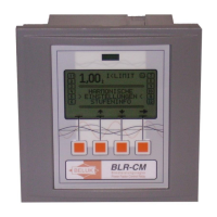
What does display "ULIMIT" mean on my Beluk Controller?
M
Marc FloresSep 1, 2025
The display 'ULIMIT' on your Beluk Controller indicates that the measurement voltage is out of range or the settings for voltage measurement are wrong. Check the correct connection of the measurement voltage and rectify if necessary. Also, check the settings in the 'SETUP / MEASUREMENT' menu and rectify if needed.
C
Christopher GarciaSep 4, 2025
Why is the control mode reversed on my Beluk BLR-CM 3 phase Controller?
M
michaelgardnerSep 4, 2025
A reversed control mode on your Beluk Controller can occur if the current or voltage clamps are interchanged. Correct the connection or adapt phase compensation.
A
andersonrobertSep 6, 2025
Why are steps detected as defective on my Beluk Controller?
D
Dr. Jonathan ThomasSep 7, 2025
If steps are detected as defective on your Beluk Controller, the step itself may be defective. Check the capacitor steps, looking for a defective fuse, capacitor, or contactor.
A
albert76Sep 9, 2025
Why are single steps not switching on or off on my Beluk BLR-CM 3 phase?
D
Darlene HuffmanSep 9, 2025
If single steps are not switching on or off on your Beluk Controller, the settings might be wrong. Check if the referring steps are defined as fix steps (permanently on or off).