EasyManua.ls Logo

Beluk BLR-CM - User Manual

Default Icon
41 pages
Print Icon
To Next Page IconTo Next Page
Loading...
Reference Manual
BLR-CM/BLR-CM3phase
Rev. 08
2018-09
Beluk GmbH
Taubenstrasse 1
86956 Schongau
Germany
Tel.: +49/(0)8861/2332-0
Fax: +49/(0)8861/2332-22
E-Mail: blr@beluk.de
Web: http://www.beluk.de
Reference Manual
Power Factor Controller
BLR-CM
BLR-CM3phase

Other manuals for Beluk BLR-CM

Questions and Answers

  • F
    finleyrobinAug 18, 2025
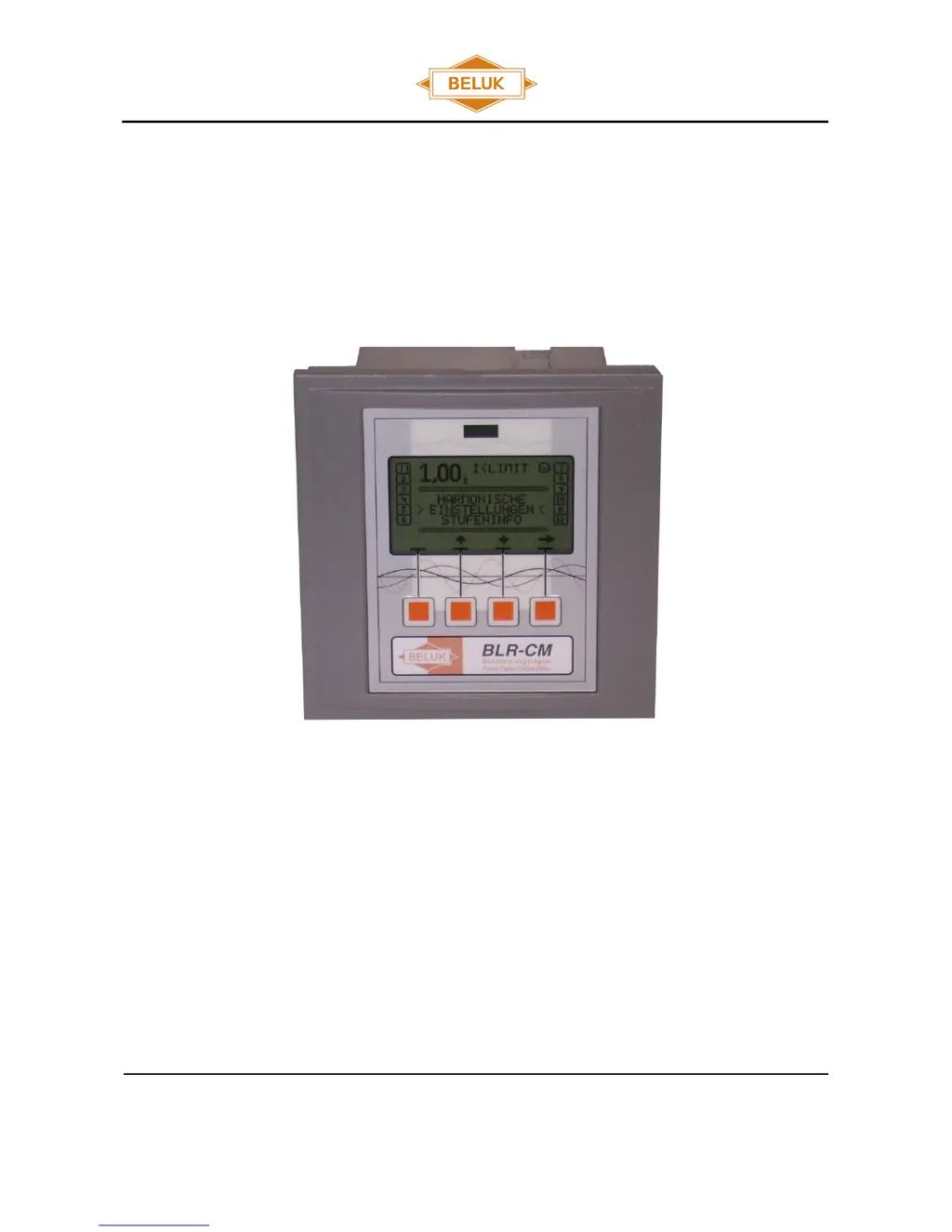
    Why is the power factor displayed incorrectly on my Beluk BLR-CM Controller?
    • M
      Morgan SchneiderAug 18, 2025
      An incorrect power factor display on your Beluk Controller can be caused by incorrect settings at the regulator. Check the 'NOMINAL VOLTAGE' and 'CONNECTION' settings in the 'SETUP' menu, and the 'PHASE COMPENSATION' setting in the 'EXTENDED' menu. Also, rectify the correct setting of Q offset if necessary.
  • N
    nancy88Aug 20, 2025
    What to do if I get an alarm "control" on my Beluk BLR-CM?
    • C
      Cody WalkerAug 20, 2025
      The 'control' alarm on your Beluk Controller indicates permanent overcompensation or undercompensation. To resolve this, check the settings, contactors (to ensure they are not stuck), capacitors (for defective fuses), and the dimensioning of the compensation unit.
  • S
    susangonzalezAug 23, 2025
    Why doesn't the power factor change and the step is switched off again after I switch on a step on my Beluk BLR-CM?
    • J
      johnbrownAug 23, 2025
      If the power factor doesn't change after switching on a step, and the step is switched off again on your Beluk Controller, the CT might be mounted in the wrong position. Check the mounting position referring to the circuit diagram, ensuring that the current of the load and capacitors are measured. Rectify if necessary.
  • H
    Heather DuncanAug 26, 2025
    How to fix wrong current or voltage display on Beluk Controller?
    • L
      lindsayponceAug 26, 2025
      If your Beluk Controller displays the current or voltage incorrectly, the transformer ratio might be wrong. Check the PT- or CT-ratio settings in the 'SETUP / MEASUREMENT' menu and rectify if necessary. Also, correct the setting of Q offset.
  • M
    Michael HenryAug 28, 2025
    What to do if my Beluk Controller displays "I
    • A
      Amanda ColemanAug 28, 2025
      If your Beluk Controller displays 'I
  • H
    hgreenAug 30, 2025
    What does alarm "overcurrent" mean on my Beluk BLR-CM Controller and how can I fix it?
    • J
      Joseph MillerAug 30, 2025
      The 'overcurrent' alarm on your Beluk Controller indicates that the current is higher than allowed. Check the CT ratio and consider replacing it with a suitable transformer type.
  • M
    Michael SpencerSep 2, 2025
    What does display "ULIMIT" mean on my Beluk BLR-CM?
    • A
      adamcraigSep 2, 2025
      The display 'ULIMIT' on your Beluk Controller indicates that the measurement voltage is out of range or the settings for voltage measurement are wrong. Check the correct connection of the measurement voltage and rectify if necessary. Also, check the settings in the 'SETUP / MEASUREMENT' menu and rectify if needed.
  • R
    Ryan ClarkSep 4, 2025
    Why is the control mode reversed on my Beluk Controller?
    • T
      Thomas WigginsSep 4, 2025
      A reversed control mode on your Beluk Controller can occur if the current or voltage clamps are interchanged. Correct the connection or adapt phase compensation.
  • A
    amontgomerySep 7, 2025
    Why are steps detected as defective on my Beluk BLR-CM?
    • K
      Kayla KingSep 7, 2025
      If steps are detected as defective on your Beluk Controller, the step itself may be defective. Check the capacitor steps, looking for a defective fuse, capacitor, or contactor.
  • L
    Lori DuncanSep 9, 2025
    Why are single steps not switching on or off on my Beluk BLR-CM?
    • M
      Matthew AndradeSep 9, 2025
      If single steps are not switching on or off on your Beluk Controller, the settings might be wrong. Check if the referring steps are defined as fix steps (permanently on or off).

Summary

Installation and Connection

Installation Guidelines

Covers general installation steps, safety precautions, and device mounting.

MENU BLR-CM

Step Information and Settings

Covers step information, types, faulty steps, switch cycles, and step values.

Quickstart Setup and Basic Configuration

Guides through initial setup, language change, and nominal voltage settings.

Advanced Setup: CT;VT, AI, Control Modes

Covers CT/VT factors, automatic initialization, and control modes.

Setup: Measurement, Compensation, and Tolerance

Details measurement settings, phase compensation, and voltage tolerances.

Step Management and Control Parameters

Manages step configuration, control logic, and related parameters.

Fast Control and Display Settings

Covers fast control features, display options, and contrast adjustment.

Alarm and Modbus Configuration

Details alarm configurations and Modbus communication settings.

Datalogger, Reset, and Manual Operation

Covers datalogger setup, reset functions, and manual operation mode.

Standard Setting

Trouble shooting

Technical Data

Beluk BLR-CM Specifications

General IconGeneral
Voltage THD<5%
DisplayLCD
CommunicationRS485, Modbus RTU
Output Current16 A
Frequency50 Hz
Storage Temperature-20°C to +70°C

Related product manuals