Commissioning Instructions
Rev. 03
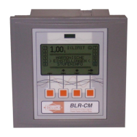
Power Factor regulator BLR-CM
Connection
Only qualified staff is
allowed to perform the
installation. All legal
rules have to be ob-
served and technical
standards have to be
met. Before connecting
the device check that all connecting leads are de-
energized and that current transformers are bypassed.
1) Compare auxiliary-, measurement-, control voltage, fre-
quency and the current path of the device (see type label)
with the data of the electricity network.
2) Assemble the relay in the switch panel with the 2 mounting
clips. If the device is not fitting in the cutout the small plas-
tic bars on the side of the case can be removed with a
knife.
3) Connect protective ground to the terminal link of the case.
4) Connect in accordance to the wiring diagram. Pay special
attention to the cross section size of the CT connections!
An integrated voltage observation with regard to the auxil-
iary voltage in BLR-CM guarantees a safety disconnection
of the capacitors in case of undervoltage. It must be en-
sured, that auxiliary voltage is taken from the identical
phase as control voltage for the contactors, to guarantee
that all switching elements are safely switched off in case of under voltage.
5) Remove short circuit links of the current transformer before commissioning!
Display
User Interface of BLR-CM is a graphical LCD and a membrane keyboard with 4 softkeys.
LCD is split into 4 areas:
Top area:
The two lines of top area are showing information about general status of the relay. The readings of this
area are always available, independent from the menu which is used. The readings of top area can be
parametered in menu SETUP/DISPLAY.
The “sad face” indicates that there are problems with the level of voltage or current.
The “happy face” indicates that levels of voltage and current are ok.
The “serious face” indicates setting PFC OFF or PFC FREEZE.
Status columns
:
left and right column are showing the status of the control exits.
1 Step 1, status: off, type: NORMAL