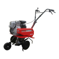
SpA BL 4000
5
START-UP STEPS
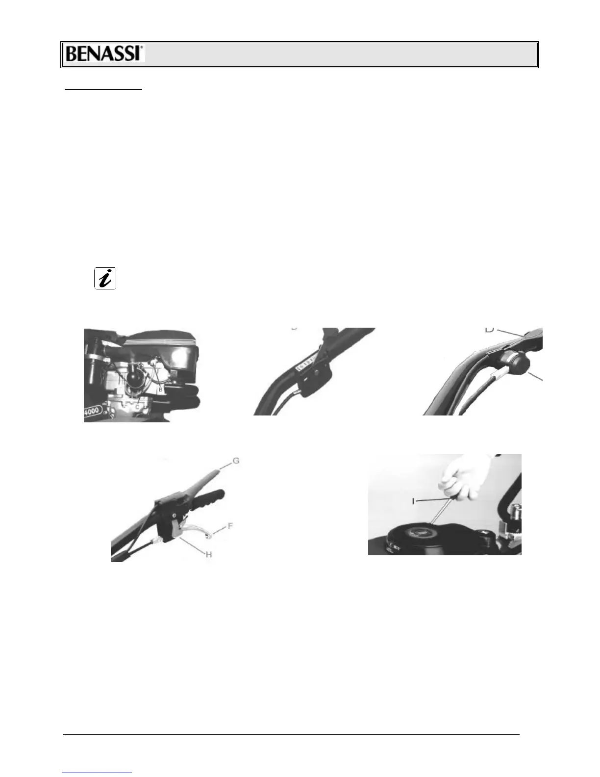
1. The petrol cock must be open. In the BL4000 e BL4000 CM screw "C" must be unscrewed (Fig. 3).
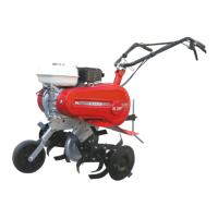
2. In the BL4000 lower the choke lever "C" (Fig. 3) and turn the accelerator hand lever "D" one quarter or in the "Start"
position (Fig. 4).
3. Ensure that the gearbox engagement lever BL4000 are in neutral.
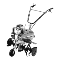
4. Keep the motor stop lever pressed down with the left hand, gripping it with the knob (Fig. Ref. "G") . Pull the engagemrnt-
disengagement lever (ref. “F”) and block both the levers with the push-button Ref. “H” Fig.5.
5. Grip the start handle "I" with one hand (Fig. 6). Pull slightly until feeling a some resistance, then pull harder. When the
motor is running, the cord should not be released suddenly, but should be guided back until it is rewound completely.
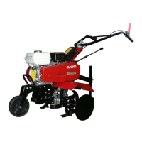
6. Once the motor is running, with the BL4000 (all models)have the accelerator lever "D" return approximately halfway (Fig.
4). In the BL4000, disconnect the choke and accelerate progressively. Warm up the motor sufficiently before starting
work.
7. To then release the two levers (see fig. 5 ref. F-G), and move forward, grasp both levers and slightly squeeze the
engagement-disengagement lever “F” Fig.5, after releasing the button (ref. H Fig.5) let the lever down and the
transmission is engaged. To shut off the motor, release the "motor stop" lever (Fig. 5 Ref. "G") and close the petrol cock.
Remember never to tie the "motor stop" lever to the handlebar knob while using the power hoe. To shut off the motor
more quickly, we suggest to push the button Ref. “E” Fig. 4 o to shift the accelerator lever to the position “OFF” “TOP”.
FOR BEST MACHINE START-UP, READ CAREFULLY THE MOTOR OPERATION AND MAINTENANCE
MANUAL UNDER THE HEADING "START UP".
-Fig. n°3- -Fig. n°4-
-Fig. n°5- -Fig. n°6-
OPERATING AND REGULATING THE MACHINE
• To have the power hoe move forward, engage the gearbox engagement-disengagement lever Fig.5 Rif.”F”
• This operation should always be carried out with the motor running at the minimum r.p.m. In any case, release the lever
slowly and always keep the "motor stop" lever pushed Fig. 5Rif.”G” increase the r.p.m. with the accelerator hand lever.
Do not let the "motor stop" lever (Fig. 5 Ref. "G") lift up or the machine will stop.
• The steering handles are adjustable in height and horizontally may be regulated by unscrewing the blocking lever Ref."L"
in Fig. 7, positioning the handle in the desired position, and then tightening the lever.
• The cutter may have a width of 62 cm with 4 hoes (2 per side) and lateral discs. It can be widened to 86 cm with the
addition of one cutter blade per side and by replacing the pin with one longer of an appropriate size
• The cutting part of the hoes must be turned toward the front of the machine. It is advised to leave the end discs mounted
on the cutters to give the machine better stability during operation.
• The spur is fixed. It’s locked by a through-screw. Fig.8.