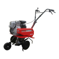
S.p.A. BL 45
5
- Picture 6 - - Picture 7 -
- Picture 8 - - Picture 9 - - Picture 10 -
USE AND ADJUSTMENT
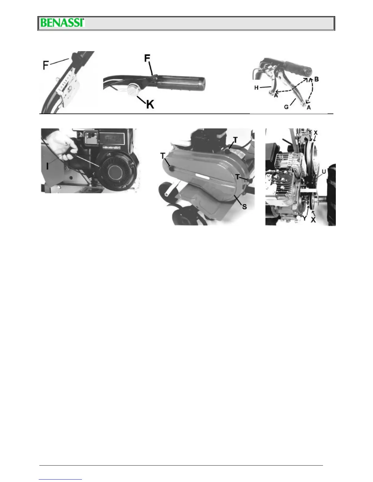
• You can start the rotation of the tiller pulling the clutch lever “G” up to position “b” (Pict. 7) the machine will immediately stop
releasing the lever.
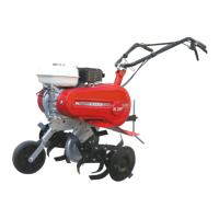
• Two speeds are available for this motorhoe going ahead: to change speed, shift the belt after taking off the belt protection
cover by unscrewing 3 knobs. (ref.”T” pict.9). Remember to switch off the engine, before doing this operation.
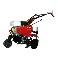
1. The speed of the motorhoe is reduced (R. P. M. 40), when the belt (ref. “U”) is in position “X” (as it’s shown in the
picture 10). Reduced speed is suggested for ploughing operations.
2. If you want the motorhoe to go faster, shift the belt (ref. “U”) into the races of the pulleys “Y”, keeping the belt stretcher
loose. This speed (R. P. M. 107) is suggested in milling operations.
• The reverse motion is engaged by pulling the “H” lever (pict. 7) in “B” position.
• Read attentively the following directions, to adjust the tension of the belts.
∗ For the high forward speed, keep the gap of about 60-70 mm between the internal sides of the belt on the axis of the
guide pulley (see picture 11), keeping the clutch lever engaged .
∗ For the reduced forward speed, keep the gap of 55-60 mm between the internal sides of the belts belt on the axis of the
guide pulley. (See picture 12)
∗ For model BL 45B: keep the gap of 25-35 mm between the internal sides of the belt on the axis of the guide pulley, see
pict. 13.
• The belt of the front gear is automatically adjusted when the reverse belt is properly adjusted.
• If the gap is not correct, you can adjust it by shifting the engine on its guides towards the handlebars if you have to reduce
the gap, or viceversa (BL 45 H excluded). After moving the engine (in all models) you should adjust the tension of the belt
stretching pulley using the adjusting screws “L” and “M” (Pict. 15), avoiding the belt sliding on the pulley.
• Guidance handlebars can be adjusted by unscrewing the blocking lever “P” (pict.16). Adjust the handlebar position as you
prefer and then lock it again.
• The tiller is 81 cm wide. It’s composed by 3 knives + protection plate, on both sides. It can be reduced to 57 cm, by removing
one tiller knife from both sides (see pictures at page 7).
• The sharp side of the hoes must be turned to the front side of the machine.
• We recommend to use the tiller with the side plates because they improve the stability of the machine and they protect from
plants and any other obstacle.
• As optional accessory, the machine can fit an adjustable lister delivered complete with its own support which should be fitted
on the rear side of the machine, replacing the standard spur.
• This machine can be used for ploughing also at reduced speed. In order to do this you have to assemble two wheel-hubs
(pict.17 ref. “P”) in the place of the tillers. Then assemble the wheels with tyres 5.0.10 on the hubs, using the screws. The
wheels are adjustable in 4 track widths.