8 CC612(4G)_D00325_06_Q_DEEN / 06.2021
CC612 Laderegler/ CC612 charge controller
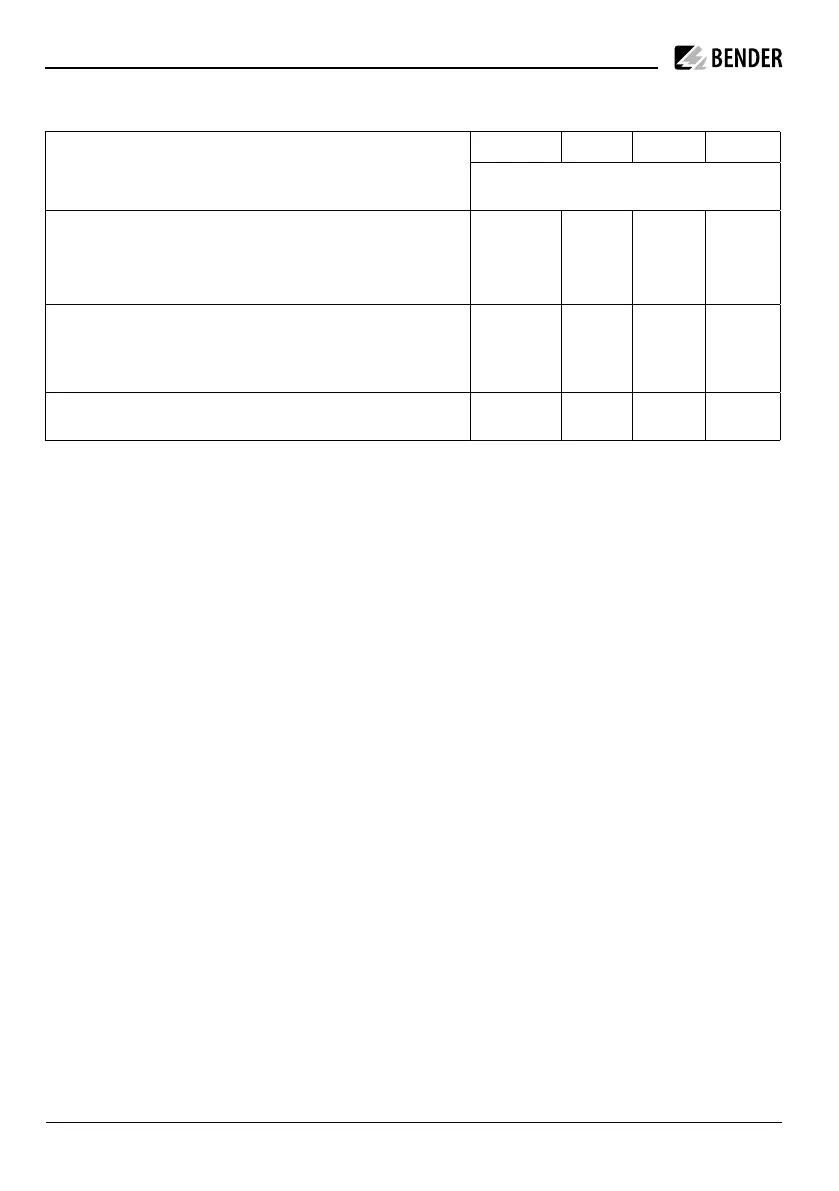
Anschluss Typ-2-Steckdose
unterstützte Typ-2-Steckdose* /
Supported Type 2 sockets*
- OUT + IN
Aktorenverdrahtung /
Socket actuator wiring
Mennekes (31016, 31023, 31024, 31038)
Bals (801191-801195, 80300, 9743205000, 9743211000)
Walther Werke (9743211000)
Harting
Draht 3
Wire 3
Draht 1
Wire 1
Draht 2
Wire 2
Walther Werke Eco Slim 32 A (9743205180)
mit Anschlusskabel (790000001)
with connection cable (790000001)
Draht 1
(schwarz)
Wire 1 (black)
Draht 3
(blau)
Wire 3
(blue)
Draht 2
(rot)
Wire 2 (red)
Phoenix Contact (1405213, 1405214, 1405215, 1405216,
1408171, 1408172)
BU/BN BU/GN BU/RD BU/YE
* Jede Typ2-Steckdose kann zusammen mit den Ver-/
Entriegelungsmodulen von Mennekes und Phoenix
Contact verwendet werden.
Fehlergleichstrom-Überwachungsmodul
(RDC-M)
Zur Fehlerstromerfassung des Wechselstrom-
Ladesystems wird ein integriertes Fehlergleichstrom-
Überwachungsmodul (RDC-M) verwendet. Dieses
nutzt einen extern angeschlossenen magnetisch ge-
schirmten Messstromwandler. Dies ermöglicht die
Verwendung einer Fehlerstrom-Schutzeinrichtung
(RCD) vom Typ A anstatt vom Typ B. Das Relais im
Laderegler fällt ab, wenn während des Ladevorgangs
ein Fehlerstrom I
Δn
≥ DC 6 mA fließt. Die gemessenen
Fehlerströme RMS/DC werden per OCPP Meldung
dem Backend-System zur Verfügung gestellt.
i
Um die elektrische Sicherheit zu gewährleisten,
werden die Abschaltzeiten gemäß IEC 62955
eingehalten.
Connection type-2-socket
* Each type 2 socket can also be used in conjunction
with lock release modules from Mennekes and
Phoenix Contact.
Residual direct current monitoring module
(RDC-M)
For fault current detection in an AC charging system,
an integrated residual direct current monitoring mo-
dule (RDC-M) is used. This module uses an external
magnetically shielded measuring current transformer.
This allows the use of a residual current device (RCD)
type A instead of an RCD type B. The relay in the char-
ge controller is de-energised if, during the charging
process, a fault current IΔn ≥ DC 6 mA flows. The
measured fault currents RMS/DC are made available
to the backend system via OCPP message.
i
To ensure electrical safety, the switch-off times
according to IEC 62955 are observed.