4
INSTALLATION
1. Install the assembled Bendix
®
AD-9
®
air dryer back onto
the vehicle by slipping it into the mounting strap and
saddle. Align the two unused holes in the end cover
with the bottom mounting bracket such that the bottom
of bracket supports the air dryer. The AD-9 air dryer end
cover should rest on the bracket. Using the remaining
two 3/8" cap screws (long), four washers and two lock
nuts, secure the air dryer to the lower bracket. Tighten,
then torque the two remaining cap screws to 270-385
in. lbs.
2. Tighten the 5/16" X 4-1/2" bolt and nut on the upper
mounting strap and saddle. Torque to 80-120 in. lbs.
3. Re-connect the three air lines to the proper ports on the
end cover assembly (identifi ed during disassembly).
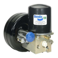
4. Re-connect the vehicle wiring harness connector to the
AD-9 air dryer heater and thermostat assembly connector
by plugging it into the air dryer connector until its lock tab
snaps in place. See Figure 5.
5. Before placing the vehicle back into service, perform the
Operation and Leakage Tests stated at the end of this
instruction sheet.
OPERATION AND LEAKAGE TESTS
1. Test the outlet port check valve by building the air
system to governor cut-out and observing a test air
gauge installed in the #1 reservoir. Check all lines and
fi ttings leading to and from the air dryer for leakage and
integrity. A rapid loss of pressure could indicate a failed
outlet check valve. To confi rmed, bleed the system down,
remove the check valve assembly from the end cover and
bench test by applying air pressure to the check valve
and soaping the other end. Leakage should not exceed
a 1" bubble in 1 second.
S-1318 © 2011 Bendix Commercial Vehicle Systems Company LLC, a member of the Knorr-Bremse Group • 6/2011 • All Rights Reserved.
2. Check for excessive leakage of the purge valve. With
the compressor loaded (compressing air), apply a soap
solution to the purge valve housing assembly exhaust
port and observe that leakage does not exceed a 1 inch
bubble in 1 second. If the leakage exceeds the maximum
specifi ed, service the purge valve housing assembly.
3. Close all reservoir drain cocks. Build up system pressure
to governor cut-out and note that AD-9 air dryer purges
with an audible escape of air. "Fan" the service brakes
to reduce system air pressure to governor cut-in. Note
that the system once again builds to full pressure and is
followed by an AD-9 air dryer purge.
4. Check the operation of the safety valve by pulling
the exposed stem while the compressor is loaded
(compressing air). There must be an exhaust of air while
the stem is held and the valve should re-seat when the
stem is released.
5. Check the operation of the end cover heater and
thermostat assembly during cold weather operation as
follows:
A. Electric Power to the Dryer (Refer to Fig. 5)
With the ignition or engine kill switch in the ON
position, check for voltage to the heater and
thermostat assembly using a voltmeter or test light.
Unplug the electrical connector at the air dryer and
place the test leads on each of the pins of the male
connector. If there is no voltage, look for a blown
fuse, broken wires, or corrosion in the vehicle wiring
harness. Check to see if a good ground path exists.
B. Thermostat and Heater Operation
Turn off the ignition switch and cool the end
cover assembly to below 40° Fahrenheit. Using
an ohmmeter, check the resistance between the
electrical pins in the female connector. The resistance
should be between 1.0 and 3.0 ohms for the 12 volt
heater assembly and 4.8 to 9.0 ohms for the 24 volt
heater assembly. If the resistance is higher than the
maximum stated, replace the heater and thermostat
assembly.
Warm the end cover assembly to over 90° Fahrenheit
and again check the resistance. The resistance
should exceed 1000 ohms. If the resistance values
obtained are within the stated limits, the thermostat
and heater is operating properly. If the resistance
values obtained are outside the stated limits, replace
the heater and thermostat assembly.
Connector
Seal
Purge Valve
Assembly
Connector
Vehicle Wiring
Harness Connector
Note: Make certain the seal is present on the vehicle wiring
harness connector. If no dielectric grease is present in the
mating connector, apply a small amount over each connector
pin before plugging in the connector.
Figure 5 Wiring Harness Connectors
 Loading...