Wheel Speed Sensors (Continued)
2 9 LF Sensor High Frequency Noise
3 9 RF Sensor High Frequency Noise
4 9 LR Sensor High Frequency Noise
5 9 RR Sensor High Frequency Noise
6 9 LM Sensor High Frequency Noise
7 9 RM Sensor High Frequency Noise
2 10 LF Sensor Wobble Run
3 10 RF Sensor Wobble Run
4 10 LR Sensor Wobble Run
5 10 RR Sensor Wobble Run
6 10 LM Sensor Wobble Run
7 10 RM Sensor Wobble Run
4 11 LR Sensor Gross Mismatch
5 11 RR Sensor Gross Mismatch
6 11 LM Sensor Gross Mismatch
7 11 RM Sensor Gross Mismatch
2 12 LF Sensor Abnormal Speed
3 12 RF Sensor Abnormal Speed
4 12 LR Sensor Abnormal Speed
5 12 RR Sensor Abnormal Speed
6 12 LM Sensor Abnormal Speed
7 12 RM Sensor Abnormal Speed
ABS Modulators
8 1 LF Modulator Lock Time Out
8 7 RF Modulator Lock Time Out
9 1 LR Modulator Lock Time Out
9 7 RR Modulator Lock Time Out
8 2 LF Modulator Open / Shorted to GND
8 8 RF Modulator Open / Shorted to GND
9 2 LR Modulator Open / Shorted to GND
9 8 RR Modulator Open / Shorted to GND
8 3 LF Modulator Shorted to Ground
8 9 RF Modulator Shorted to Ground
9 3 LR Modulator Shorted to Ground
9 9 RR Modulator Shorted to Ground
8 4 LF Modulator Shorted Solenoid
8 10 RF Modulator Shorted Solenoid
9 4 LR Modulator Shorted Solenoid
9 10 RR Modulator Shorted Solenoid
8 5 LF Modulator Shorted to VBAT
8 11 RF Modulator Shorted to VBAT
9 5 LR Modulator Shorted to VBAT
9 11 RR Modulator Shorted to VBAT
ABS Modulators (Continued)
8 6 LF Modulator Shorted Between
8 12 RF Modulator Shorted Between
9 6 LR Modulator Shorted Between
9 12 RR Modulator Shorted Between
Retarder Relay Control
10 1 Retarder Relay Open
10 2 Retarder Relay Shorted
ATC - Traction Control
10 5 Traction Modulator Open
10 6 Traction Modulator Shorted to Ground
10 7 Traction Modulator Shorted
10 8 Traction Modulator Shorted to VBAT
Lamps
10 9 Traction Lamp Open
10 10 Traction Lamp Shorted
10 11 ABS - Warning Lamp Open
10 12 ABS - Warning Lamp Shorted
11 1 Trailer ABS - Warning Lamp Open (Dash Mounted)
11 2 Trailer ABS - Warning Lamp Shorted (Dash Mounted)
Engine Serial Communications
11 3 J1939 Data Link Retarder Communication Fault
11 4 J1939 Data Link Engine Communication Fault
11 5 J1922 Data Link Engine Communication Fault
11 6 J1922 Data Link Retarder Communication Fault
M-30
modulator
™
C1-D1
C1-E1
D1-E1 7.0
3.5-5.0 Ohms
3.5-5.0 Ohms
-10.0 Ohms
M-32
modulator
™
4.9-5.5
4.9
9.8
Ohms
-5.5 Ohms
-11.0 Ohms
M-30
modulator
™
H1-G1
H1-F1
G1-F1 7.0
3.5-5.0 Ohms
3.5-5.0 Ohms
-10.0 Ohms
M-32
modulator
™
4.9-5.5
4.9
9.8
Ohms
-5.5 Ohms
-11.0 Ohms
M-30
modulator
™
A1-B1
A1-C1
B1-C1 7.0
3.5-5.0 Ohms
3.5-5.0 Ohms
-10.0 Ohms
M-32
modulator
™
4.9-5.5
4.9
9.8
Ohms
-5.5 Ohms
-11.0 Ohms
M-30
™
modulator
F1-E1
F1-D1
E1-D1 7.0
3.5-5.0 Ohms
3.5-5.0 Ohms
-10.0 Ohms
M-32
modulator
™
4.9-5.5
4.9
9.8
Ohms
-5.5 Ohms
-11.0 Ohms
BW2175 © 2010 Bendix Commercial Vehicle Systems LLC • All Rights Reserved • Printed in U.S.A. 9/10
Press the Blink
Code Switch
1time
2times
3times
4times
Blink Code Action
Display Active DTC Codes
Display DTC Code History
Reset Active DTC Codes
Display EC-30 Configuration
1st Digit
2nd Digit
3rd Digit
2
3
2
2
3
4
5
Sensors
Modulators
ATC
4 Sensors
6 Sensors
4 Modulators
Not ATC
ATC Engine Torque Limiting Only
ATC Differential Brake Only
Full ATC (Engine Torque Limiting
and Differential Braking)
Display DTC Code History
Reset Active DTC Codes
To display history DTCcodes, press the blink code switch two times.
Following activation, there will be a 3 second delay followed by a blink
code display of all history DTCcodes.
To reset active DTCcodes, press the blink code switch three times.
Following activation, there will be a 3 second delay followed by a blink
code message of:
1-1, (System Fully Operational - No DTCs Detected)
or,
A blink code display of all active DTC codes.
The ABS warning lamp will stay on if active DTCs are still present.
Resetting active DTCcodes with blink code diagnostics does not clear
information from DTChistory. DTC history can be retrieved by using
blink code diagnostics or by using a diagnostic tool.
Display Active DTC
Codes
To display active DTC
codes, press the blink
code switch one time.
Following activation,
there will be a 3 second
delay followed by a
blink code display of all
active DTCcodes.
Display EC-30
Controller
Configuration
™
To check the ECU
configuration, press the
blink code switch four
times. Following
activation, there will be
a 3 second delay
followed by a blink code
display of the EC-30
configuration.
™
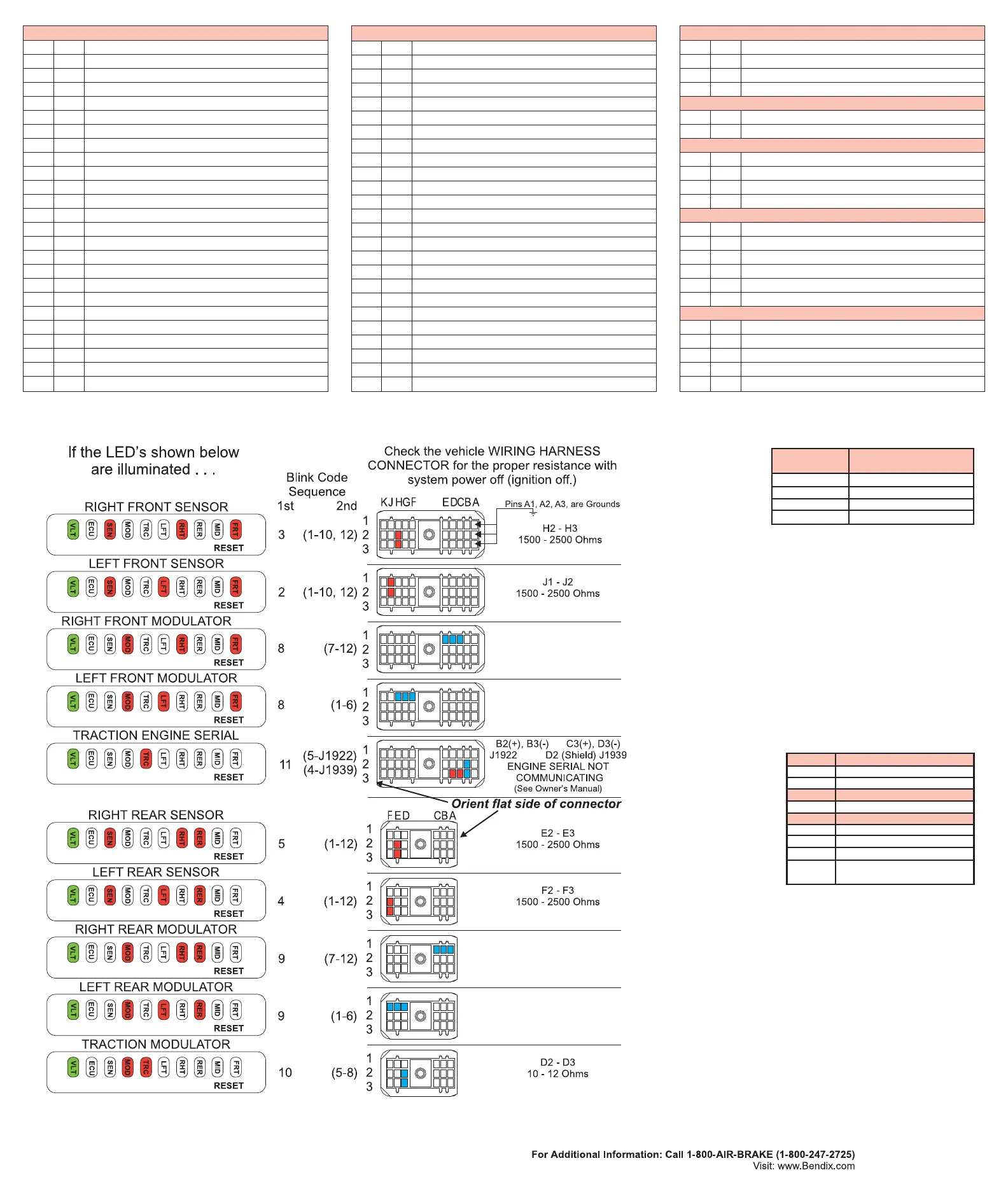
Most Commonly Encountered Problems
That Result In LED’s Being Illuminated
Repair or Replace Components as Necessary
If Traction Dash Lamp Only Illuminated, Check/Repair These Items
First:
1. Abraded or cut wires in the convoluted tubing near frame clamps.
2. Cut or corroded wires near sharp frame members and frame mounted
modulators.
3. Wire jacket worn through from overlapping sensor and modulator
wires near frame members and frame mounted modulators.
4. Corroded connectors and connections not properly sealed or damaged
seals.
5. Damaged connector latches or connectors not completely seated to
mating assemblies.
6. Terminals not completely latched or seated into connectors.
7. Excessive sensor air gap, sensor clip tension, or excessive bearing
end play (gently push sensor against wheel hub, or readjust bearings.)
8. Damage to exposed wires exiting or entering the convoluted tubing.
9. Worn, chipped or damaged sensor or modulator.
10. Non functioning antilock controller.
1. Traction enable/disable switch in wrong position.
2. Loss of traction engine serial communication (check service manual).
3. Traction solenoid not connected, or exceeds resistance range.
Contacts above should have no continuity to ground, except contacts A1, A2, A3
of 30-pin connector. Contacts B1, K2, and K3 supply power to the EC-30 controller connector
™
Products shown on this document may be covered by one or more of the following
Patents: 6254048, 6324468, 6209971, 4837552, 5341298, 5613744, 6237401.
 Loading...


