7
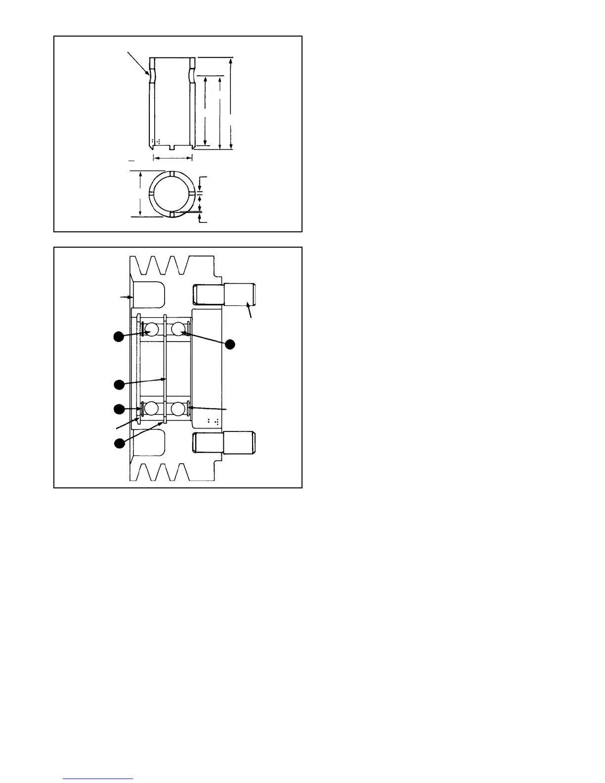
FIGURE 10
MATERIAL O.H.T.S. TUBING
HDN. & DRAW. RC 40-45
27/32” DRILL THRU
(2 HOLES FOR 3/4”
BAR”
2-3/4”
.235 + - .002 CENTERED
(4 LUGS)
FIGURE 11
DRIVE PINS
PULLEY
22
19
SEAL
19
20
21
SEAL
Displace the bearing spacer(12) so that it is eccentric
to the bearing bore as far as possible. Insert a round
pressing tool through the I.D. of the ball bearing(13)
until it contacts the spacer(12). Press the ball
bearing(11) and the bearing spacer(12) out of the fan
plate. Discard the bearing because it will be damaged
by disassembly.
2. Remove retaining ring(14) using Waldes tool #6500.
Turn fan plate over and press out remaining bearing(13).
Discard the bearing.
FAN PLATE DISASSEMBLY WITH PILOT
DIAMETER OF 2.560
1. Remove the retaining ring(14) from the fan plate. Place
the fan plate on a firm surface and utilizing a round
pressing tool, press out the two ball bearings(13) and
the spacer(12). Discard the bearings.
REASSEMBLY
ASSEMBLY OF PULLEY (Refer to Figure 11)
1. Install snap ring(21) using Waldes tool #6500 or
equivalent.
2. Support the pulley on the drive pin end and press one
of the bearings(19) (seal side up) into the pulley until it
contacts the snap ring(21). Use a pressing tool that
contacts the outer race of the bearing.
3. Turn the pulley over and position the spacer(20)
concentric with the inner race of the previously installed
bearing. Pack grease (Exxon Unirex N-2 or equivalent)
around the spacer making certain not to overfill the
volume. Support both the inner and outer race of the
previously installed bearing. Press in second
bearing(19) (seal side up) using a tool that contacts
both the inner and outer race until the inner race of the
bearing contacts the spacer(20).
4. Turn the pulley over and install the tapered snap ring(22)
(flat side towards the bearing) making sure the snap
ring is fully seated in its groove.
ASSEMBLY OF PULLEY ONTO THE BRACKET
AND SHAFT
1. Support the bracket with the shaft pointing up. Apply
one bank of Loctite RC609 around the shaft at the
location of inner races of the bearings(19) in the pulley.
Also put a band of the Loctite on the inner races of the
bearings(19). NOTE: Parts must BE free of oil and
grease for Loctite to properly bond.
2. Slide the pulley onto the shaft, making sure the bottom
bearings inner race(19) contacts the bracket. Allow 24
hours for complete curing of the Loctite to take affect.
3. Place locking ring(23) on the shaft and install locknut(18)
using the same tool as Step 12 of ‘Disassembly’. Torque
locknut to 100-150 ft. lbs. until one of the tangs of the
lockring(23) can be bent up into one of the slots of the
locknut. Never back the torque off to align parts.
ASSEMBLY OF FAN PLATE WITH 1.998 PILOT
DIAMETER
1. Support the fan plate on the fan mounting surface (nose
down) and press bearing (13) into the housing until it
bottoms against the shoulder of the fan plate. NOTE:
Use a pressing tool that contacts the outer race of the
bearing, do not use a load greater than 1100 lbs. to
press bearing into bore.
2. Turn fan plate over and fully support the previously
installed bearing (13) both inner and outer race. Install
spacer (12) concentric with the inner race of bearing
(13). Press in bearing (11) with a tool that contacts
both the inner and outer race and with a force no greater
than 1100 lbs. until the inner race contacts the spacer.
2.125 + .010
1/32” FLAT