8
FIGURE 12
The spacer (12) should be tight against both bearing
inner races, yet be able to be moved by a finger load.
3. Turn the fan plate over and install snap ring (14) with the
flat side towards the bearing, making certain the snap
ring is fully seated in its groove.
ASSEMBLY OF FAN PLATE WITH 2.560 PILOT
DIAMETER
1. Support the fan plate on the fan mounting surface (nose
down). Using a pressing tool that contacts the outer
bearing race only, press ball bearing (13) into the fan
plate using a force no greater than 1100 lbs. Until it
contacts the fan plate shoulder. Install the bearing
spacer(12) (as illustrated in Figure 1) concentric with
the inner race of the ball bearing previously installed.
2. Continue to support the fan plate (nose down) and press
bearing (11) using a pressing tool that contacts the outer
race of the bearing only. Carefully press the bearing
with a force no greater than 1100 lbs. until the inner
bearing race contacts spacer (12). Do not continue
pressing the bearing once the inner race has touched
the spacer; severe damage to the bearings may result.
As a check after assembly, the bearing spacer should
be tight against each bearing race yet able to be moved
by a finger load.
3. Turn the fan plate over and install snap ring (14) with
the flat side towards the bearing, making certain the
snap ring is fully seated in its groove.
FINAL ASSEMBLY
1. Support the bracket, shaft, and pulley assembly with
the shaft pointing up.
2. Install spring pack (9) onto the pulley assembly and
retain with the two 1/4"x20 Phillips screws. Torque to
50-75 inch pounds.
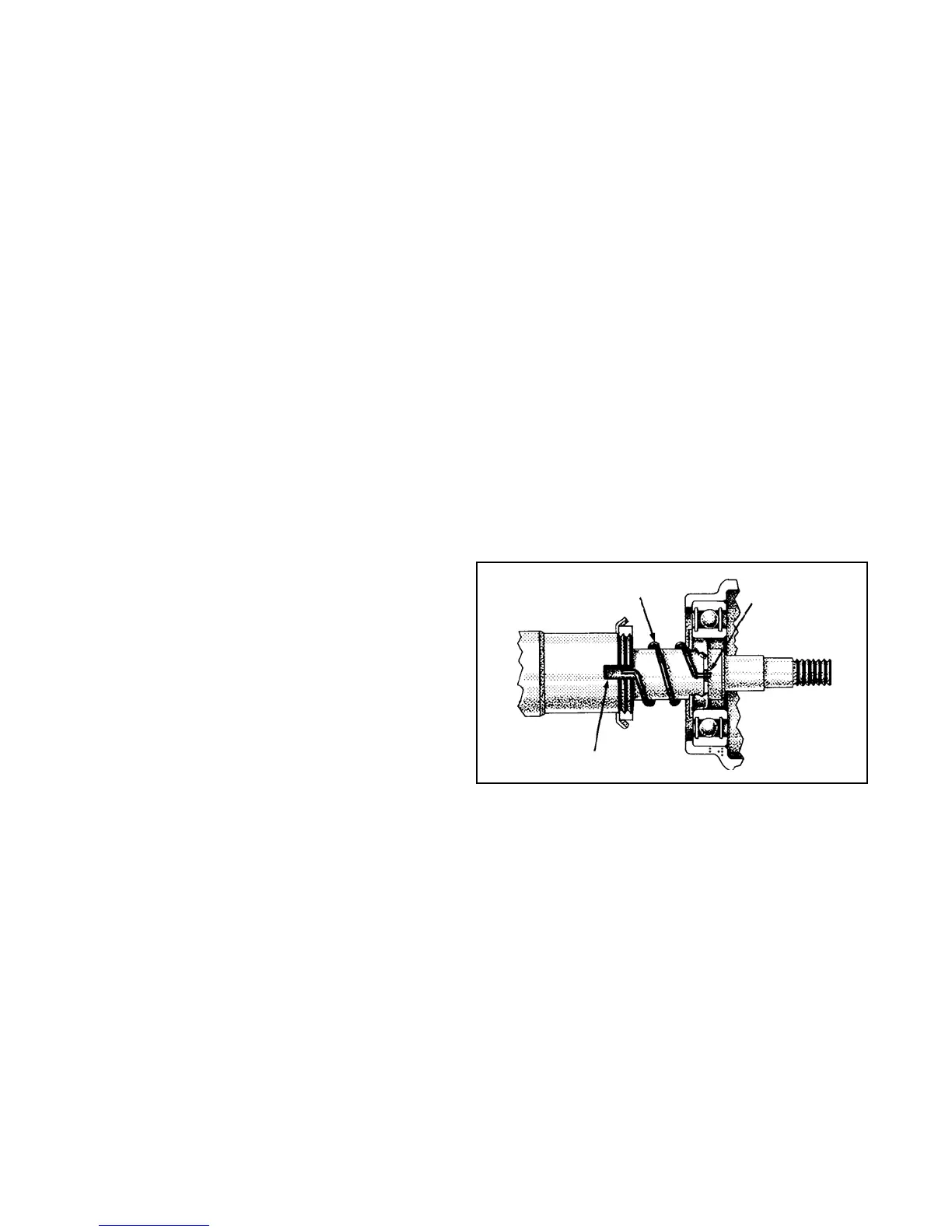
3. Install the anti-rotational spring(17) making sure one
end of the spring is engaged in the notch of the shaft.
(See Figure 12)
4. Apply a thin film of silicone lubricant BW-655M to the
four o-rings(6). Position the o-rings into the grooves
located in the drive pin holes of the pressure plate(7).
Apply the same lubricant to the drive pins on the pulley.
5. Install the pressure plate(7) onto the pulley assembly
making sure the end of the antirotational spring(17) is
engaged in the notch of the spring collar on the I.D. of
the pressure plate. Holes in the pressure plate must
slide over the drive pins.
6. Lubricate the I.D. of the piston housing(15) and the
three o-rings (3,4, & 5) with lubricant used in Step 4.
Install o-rings (4&5) onto the piston and o-ring (3) onto
the shaft.
7. Install piston(16) into the piston housing(15) and install
unit onto the shaft.
8. Install fan plate assembly onto the shaft and retain with
the locknut(10). NOTE: On unit with 2.560 diameter
hub, washer(11) to be installed before the locknut. Torque
to 90 to 100 ft.lbs.
9. Install cotter pin(2) and bend to hold in place. Replace
cap(1).
INSTALLATION
1. Attach fan clutch unit to vehicle by installing cap nuts
and lockwashers through mounting bracket holes into
mating holes in engine bracket.
2. Reconnect air line to unit.
3. Adjust fan belts per vehicle manufacturer’s
recommendation.
4. Replace fan on pressure plate with six cap screws and
lockwashers. Torque to 300-360 inch pounds. (Be sure
to install any spacers that were removed during
disassembly.)
5. Perform service checks as previously outlined.
TEST
1. With no air pressure applied, the torque required to rotate
the clutch must not exceed 150 in. oz.
2. With 70-75 psi applied, the fan plate must separate from
the pulley and rotate freely.
3. Perform the leakage checks outlined in the manual.
RETROFIT INSTALLATION
INFORMATION
To determine which fan clutch piece number should be
purchased when retrofitting existing equipment, consult the
nearest authorized Bendix distributor for assistance.
Complete installation instructions and piping diagrams are
packed with each FD-3
™
TorqueMaster fan clutch.
It is recommended that only cooling fans approved by the
vehicle or fan manufacturer be installed on the
FD-3
™
TorqueMaster.
Maximum weight of fan blade assembly is 30 lbs.
Maximum R.P.M. of 28 inch fan is 2700.
Maximum R.P.M. of 34 inch fan is 2100.
Maximum thickness of spacers between fan and hub plate
is 1-1/2".
ANTI-ROTATIONAL
SPRING
ONE END OF SPRING
INSTALLED IN NOTCH
IN SPRING COLLAR
ONE END OF SPRING INSTALLED
IN NOTCH OF THE SHAFT
BW1452 © 2004 Bendix Commercial Vehicle Systems LLC All rights reserved. 4/2004 Printed in U.S.A.