3
DRIVER ASSISTANCE FEATURES
LANE KEEP ASSIST (LKA)
• Detects lane markings and evaluates relative vehicle
position
• Recognizes when the vehicle begins to drift towards
the lane markings
• Distinguishes between planned lane changes and
lane drifting
• Intervenes before the vehicle reaches the lane markings
• Automatically applies a correction torque to the steering
wheel
• Smoothly releases steering torque as soon as the
vehicle trajectory is re-established
• The system enables the driver to suppress or override
steering torque
• LKA is activated at 37 mph / 60 kph
STEERING ASSIST
• Speed Dependent Steering Assist - Provides variable
steering assist based on vehicle speed. It helps the
driver experience easier steering at low speeds and
a rmer steering response at higher speeds. It also
aids the driver by reducing fatigue and helps the driver
maintain better control of the vehicle.
• Active Return - Helps to reduce driver fatigue through
easier maneuvering by returning the steering wheel to
the center position at lower vehicle speeds.
• Crown/Side-Wind Compensation - Helps to reduce
driver fatigue, or steering eort, by helping keep the
vehicle straight during heavy side winds, crowned
roads, or some alignment issues.
• Road Disturbance Compensation - Helps improve
driver comfort by reducing steering wheel vibration
typically caused by road disturbances like potholes,
road debris, or other bumps in the road.
SYSTEM COMPONENTS
BENDIX
®
AUTOVUE
®
FLC-20
™
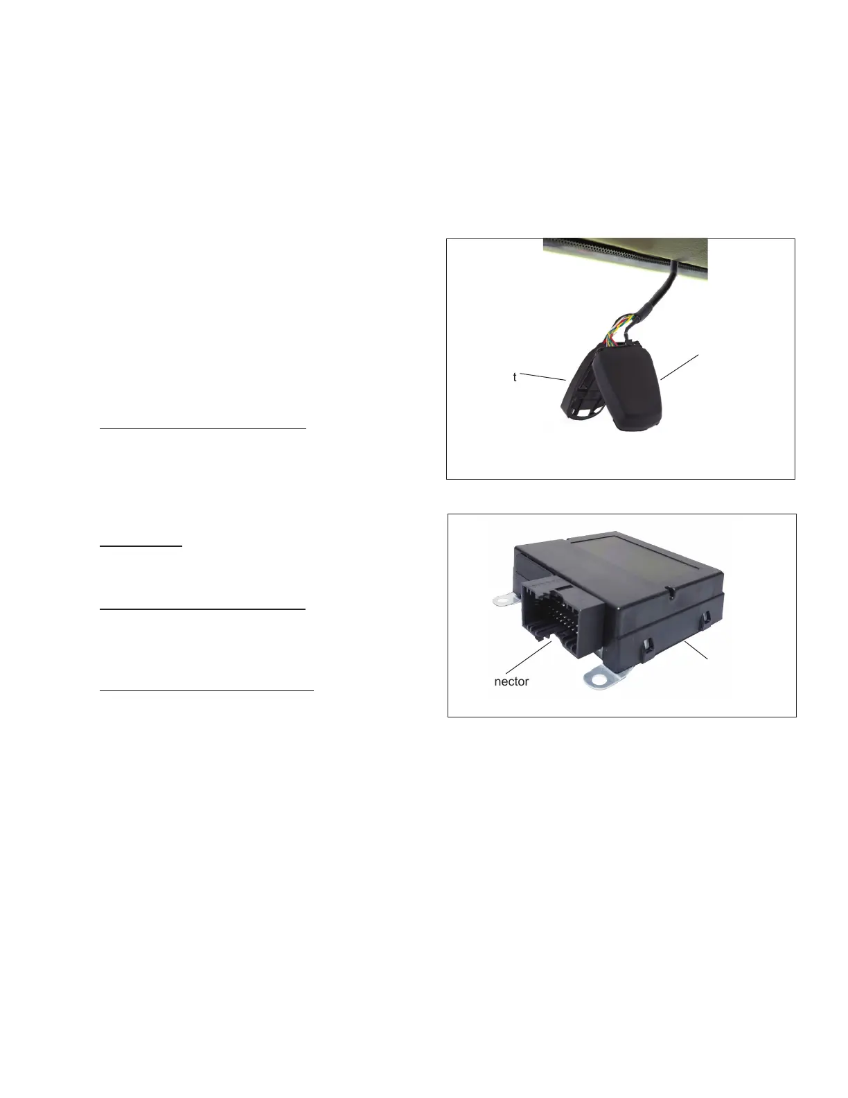
CAMERA
• The forward-facing camera tracks the lane markers and
provides the lane characteristics for the left and right
marker to the Sheppard
®
Active Steering System by
Bendix CVS system over the vehicle communication
network. In addition, the system also provides
information on when the lane departure warnings
will be suppressed, allowing the LKA feature to be
suppressed at the same time. See Figure 3.
• For additional information, see the Bendix
®
AutoVue
®
FLC-20
™
Camera Service Data sheet SD-64-20124
available for download on bendix.com.
• Is compatible with later versions of Bendix
®
Wingman
®
Fusion
™
systems.
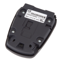
LDW WINDSHIELD MOUNTING BRACKET
• The bracket that holds the camera secure and keeps
it facing the correct direction to successfully determine
lane width and position. See Figure 3.
Figure 3 – Bendix
®
AutoVue
®
FLC-20
™
Camera & Bracket
Bendix
®
AutoVue
®
FLC-20
™
Camera
Camera
Bracket
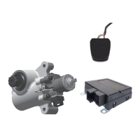
ACTIVE STEERING ECU
• The Electronic Control Unit (ECU) for the Sheppard
Active Steering System by Bendix CVS is a standalone
unit designed to work with J1939 Vehicle CAN and a
forward-facing lane sensing camera. See Figure 4.
Figure 4 – Lane Keep Assist Electronic Control Unit (ECU)
ECU
Connector
 Loading...