EasyManua.ls Logo

BENDIX SLACK ADJUSTERS User Manual

BENDIX SLACK ADJUSTERS
6 pages
To Next Page IconTo Next Page
Page #1 background imageLoading...
Page #1 background image
1
Bendix Manual Slack Adjusters
SD-05-1200
FIGURE 1 - POSITIVE LOCK TYPE SLACK ADJUSTER
DESCRIPTION
In an s-cam type foundation brake, the final link between
the pneumatic system and the foundation brake is the slack
adjuster. The arm of the slack adjuster is fastened to the
push rod of the chamber with a yoke, and the slack adjuster
spline is installed on the brake cam shaft.
Primarily, the slack adjuster is a lever, converting the linear
force of the air chamber push rod into a torque which turns
the brake cam shaft and applies the brakes.
Standard slack adjusters contain four basic components;
the body, worm, gear and adjusting screw. The adjusting
screw is provided to adjust the slack caused by the wear of
the brake lining.
All slack adjusters utilize the worm and gear principle and,
fundamentally, differ only in torque limit specifications; A
type 20 slack adjuster has a limit of 20,000 inch pounds
torque, a type 30 slack adjuster has a limit of 30,000 inch
pounds torque, etc.
Slack adjusters are manufactured with various arm lengths
and various configurations; straight, offset, etc. to satisfy
various installation requirements. Splines are available in
several different types and sizes.
OPERATION
When the brakes are applied, air pressure forces the air
chamber diaphragm and push rod to move; this rotates the
slack adjuster, which in turn rotates the cam shaft. This
causes the “S” cam to spread the brake shoes which contact
the brake drum.
When the brakes are released, air pressure is exhausted
from the air chamber. The chamber return spring and the
brake shoe return springs return the brake cam, cam shaft,
slack adjuster and chamber push rod to the released position.
ADJUSTING MECHANISM
The adjusting mechanism of a slack adjuster consists of an
adjusting screw (worm shaft), worm and slack adjuster worm
gear. Turning the adjusting screw nut on the end of the worm
shaft rotates the worm shaft and worm. The worm meshes
with and rotates the slack adjuster worm gear which is
connected to the brake cam by a splined cam shaft. The
turning of the slack adjuster worm gear rotates the cam
shaft and brake cam, spreading the brake shoes,
compensating for brake lining wear.
There are two types of adjusting mechanisms used on Bendix
slack adjusters currently manufactured. The light to medium
torque rated slack adjusters (Fig. 1) use a positive lock
mechanism consisting of a spring loaded lock sleeve, which
when positioned properly, engages the adjusting screw nut,
preventing the adjusting screw (worm shaft) from rotating.
The heavier torque rated slack adjusters (Fig. 2) utilize the
lock ball or plunger and worm shaft indent principle
adjustment lock. The lock ball or plunger must engage the
indent on the worm shaft after the adjustment is completed.
An audible metallic click can be heard when engagement is
made.
WORM GEAR
LOCK SLEEVE
ADJUSTING SCREW
(WORM SHAFT)
ADJUSTING GEAR
GREASE HOLE
SPLINE
WORM GEAR
SPLINE
ADJUSTING SCREW
(WORM SHAFT)
ADJUSTING
GEAR
WORM SHAFT (LOCK
SCREW)
FIGURE 2 - BALL INDENT TYPE SLACK ADJUSTER
Question and Answer IconNeed help?

Do you have a question about the BENDIX SLACK ADJUSTERS and is the answer not in the manual?

BENDIX SLACK ADJUSTERS Specifications

General IconGeneral
BrandBENDIX
ModelSLACK ADJUSTERS
CategoryAutomobile Parts
LanguageEnglish

Summary

Slack Adjuster Fundamentals

Description

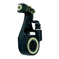
Explains the slack adjuster's role as a lever converting linear force to torque in brake systems.

Operation

Details how slack adjusters function during brake application and release cycles.

Adjusting Mechanism Types

Describes the components and two main types of slack adjuster adjustment mechanisms.

Slack Adjuster Adjustment and Checks

Adjustment Procedures

Step-by-step guides for using positive lock and ball indent slack adjuster mechanisms.

Brake Adjustment Check

Methods to verify correct brake adjustment using push rod stroke measurements.

Brake Adjustment Methods

Preferred and alternate methods for adjusting slack adjusters for optimal performance.

Preventive Maintenance

Service Intervals

Recommendations for monthly checks and semi-annual lubrication of slack adjusters.

Slack Adjuster Mounting, Service, and Replacement

Mounting Orientations

Discusses tension vs. compression mounting for slack adjusters and their implications.

Lubrication Procedures

Instructions for lubricating slack adjusters lacking a dedicated fitting.

Service Tests

Procedures for testing slack adjuster operation after installation or repair.

Replacement Considerations

Factors to consider when substituting slack adjuster types for compatibility.

Slack Adjuster Removal and Installation

Removal Steps

Detailed instructions for safely removing a slack adjuster from the vehicle.

Installation Steps

Detailed instructions for safely installing a slack adjuster onto the vehicle.

Disassembly and Assembly

Type 20-30 Positive Lock Disassembly

Steps for disassembling a Type 20-30 slack adjuster with a positive lock mechanism.

Disassembly Procedures

Type 20-30 Positive Lock Disassembly

Detailed steps for disassembling Type 20-30 slack adjusters with positive lock.

Type 35 Positive Lock Disassembly

Steps for disassembling Type 35 slack adjusters with a positive lock mechanism.

Type 35/55 Ball Indent Disassembly

Steps for disassembling Type 35/55 slack adjusters with ball indent lock mechanism.

Type 35/40/55 Ball Indent Disassembly

Steps for disassembling Type 35/40/55 slack adjusters with ball indent lock mechanism.

Assembly Procedures

Type 20-30 Positive Lock Assembly

Steps for assembling Type 20-30 slack adjusters with positive lock mechanism.

Type 35 Positive Lock Assembly

Steps for assembling Type 35 slack adjusters with positive lock mechanism.

Assembly and Safety Guidelines

Type 35/55 Ball Indent Assembly

Steps for assembling Type 35/55 slack adjusters with ball indent lock mechanism.

Type 35/40/55 Ball Indent Assembly

Steps for assembling Type 35/40/55 slack adjusters with ball indent lock mechanism.

General Safety Precautions

Essential safety guidelines to follow when working on vehicles and air brake systems.

General Safety and Component Guidelines

Vehicle Safety

Precautions for parking, blocking wheels, and engine operation during work.

Component Handling

Guidelines on proper tool usage, pressure depletion, and using genuine replacement parts.

Component and System Integrity

Component Replacement

Policy on replacing damaged or stripped threaded components rather than repairing.

Pre-Service Checks

Ensuring all components and systems are in proper operating condition before returning to service.

Antilock Traction Control (ATC)

Procedure for disabling ATC function during specific vehicle maintenance operations.

Related product manuals