EasyManua.ls Logo

BENDIX GEN 4 GEN 5 ABS User Manual

BENDIX GEN 4 GEN 5 ABS
48 pages
To Next Page IconTo Next Page
Page #1 background imageLoading...
Page #1 background image
1
®
SD-13-4746
GEN 4
AND GEN 5
ABS INTRODUCTION
This manual describes both the cab mount and the frame
mount versions of the Bendix
®
Gen 4
and Gen 5
Antilock
Brake System/Automatic Traction Control (ABS/ATC)
systems.
Both cab and frame mount versions are designed for:
Tractors
Trucks
Buses and
Motor Coaches and
RVs.
This manual covers:
ABS/ATC Operation
System Components
Service Procedures
Diagnosis and
Troubleshooting Procedures.
For information on disassembly, installation, and service of
related axle and brake components, refer to their individual
Bendix Service Manuals.
For assistance in your area call Bendix at 1-800-247-2725
or RoadRanger
®
at 1-800-826-4357.
These ABS controllers and systems were originally
marketed by Eaton Corporation under the Eaton
®
brand
name. For more information contact Bendix, your local
authorized Bendix dealer, or RoadRanger
®
.
Document Revision Level
This document is subject to revision.
For updates, please visit www.bendix.com.
Bendix
®
Gen 4
and Gen 5
ABS for Trucks, Tractors, and Buses
FIGURE 1 - Bendix
®
ABS Controller Assemblies
Cab-Mounted Models
Frame-Mounted Model
Table of Contents
ABS Operation . . . . . . . . . . . . . . . . . . . . . . . . . . . . . . . 2
ABS Component Function . . . . . . . . . . . . . . . . . . . . . . 3
ABS Indicator Lamp . . . . . . . . . . . . . . . . . . . . . . . . . . . 3
ABS Trailer Indicator Lamp . . . . . . . . . . . . . . . . . . . . . 3
Automatic Traction Control (ATC) System . . . . . . . . . . 4
Component Overview . . . . . . . . . . . . . . . . . . . . . . . . . 5
Electronic Control Units (ECUs) . . . . . . . . . . . . . . . . . 7
ABS Valves . . . . . . . . . . . . . . . . . . . . . . . . . . . . . . . . . 9
Modulator Valve Operation Modes . . . . . . . . . . . . . . . 10
Optional Front Axle Modules . . . . . . . . . . . . . . . . . . . 11
Diagnostics . . . . . . . . . . . . . . . . . . . . . . . . . . . . . . . . 13
Troubleshooting Procedures . . . . . . . . . . . . . . . . . . . 13
System Configurations . . . . . . . . . . . . . . . . . . . . . . . 15
ServiceRanger PC Software . . . . . . . . . . . . . . . . . . . 16
Test Equipment . . . . . . . . . . . . . . . . . . . . . . . . . . . . . 16
Reading Configuration Codes . . . . . . . . . . . . . . . . . . 18
Retrieving Diagnostic Trouble Codes . . . . . . . . . . . . . 18
Clearing Diagnostic Trouble Codes and/or System
Configuration . . . . . . . . . . . . . . . . . . . . . . . . . . . . . 20
Disabling ATC for Dyno Testing . . . . . . . . . . . . . . . . . 20
Speed Sensor Troubleshooting . . . . . . . . . . . . . . . . . 25
The 17•12 Sensor Memory Diagnostic Trouble Code 26
Wheel End Speed Sensor Repair . . . . . . . . . . . . . . . 28
Pressure Modulator Valve (PMV) Troubleshooting . . 30
ABS Modulator Valve . . . . . . . . . . . . . . . . . . . . . . . . . 33
Automatic Traction Control (ATC) Valve
Troubleshooting . . . . . . . . . . . . . . . . . . . . . . . . . . . 34
Performance Test of the Relay Valve . . . . . . . . . . . . . 34
ATC Valve Removal . . . . . . . . . . . . . . . . . . . . . . . . . . 36
Cab Mount ECU Pin Identification . . . . . . . . . . . . . . . 39
Frame Mount ECU Pin Identification . . . . . . . . . . . . . 43
Eaton
®
, RoadRanger
®
, and ServiceRanger
®
are registered
trademarks of Eaton Corporation.
Question and Answer IconNeed help?

Do you have a question about the BENDIX GEN 4 GEN 5 ABS and is the answer not in the manual?

BENDIX GEN 4 GEN 5 ABS Specifications

General IconGeneral
BrandBENDIX
ModelGEN 4 GEN 5 ABS
CategoryAutomobile Parts
LanguageEnglish

Summary

GEN 4 AND GEN 5 ABS INTRODUCTION

ANTILOCK BRAKING SYSTEM (ABS)

ABS Operation

Explains how the ABS system controls braking and vehicle stability during operation.

ABS Component Function

Details the sequential operation of ABS components and their roles in system function.

ABS Indicator Lamp

Describes the function, behavior, and meaning of the primary ABS status indicator lamp.

ABS Trailer Indicator Lamp

Explains the function of the trailer ABS indicator lamp on the tractor cab.

Automatic Traction Control (ATC) System

ATC Operation

Describes how the ATC system operates at different vehicle speeds and conditions.

Component Function

Details the function of specific ATC components like the ATC valve and ECU.

Thermal (Brake Heat) Protection

Explains ATC's role in preventing excessive brake and drum temperatures.

ATC Indicator Lamp

Describes the function and behavior of the ATC indicator lamp.

Component Overview

Electronic Control Unit (ECU)

Describes the ECU's role in monitoring, controlling, and diagnosing ABS malfunctions.

Pressure Modulator Valve (PMV)

Explains the PMV's function in regulating brake chamber air pressure.

Rear Axle Valve Assembly

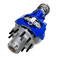
Describes the assembly combining modulator and relay valves for rear axles.

Wheel End Speed Sensor

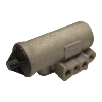
Details the sensor that monitors wheel rotation speed for ABS.

ABS Lamp (Yellow)

Describes the ABS indicator lamp for driver warnings and diagnostic codes.

In-Cab ABS Trailer Lamp

Explains the function of the trailer ABS indicator lamp.

ATC Valve

Describes the valve used for traction control brake applications.

ATC Lamp

Details the indicator lamp for traction control system status.

Relay/Breaker Panel

Describes the panel containing circuit protection for ABS components.

Diagnostic Port Connector

Explains the standard connector for diagnostic equipment.

Electronic Control Units (ECUs)

Identification

Provides information to identify different ECU part numbers and configurations.

ABS Valves

Rear Axle Valve Assemblies

Describes assemblies combining modulator and relay valves for rear axles.

Modulator Valve Operation Modes

Optional Front Axle Modules

Speed Sensors

Wheel End Sensors

Describes the wheel-end mounted sensors used for speed detection.

DIAGNOSTICS

Troubleshooting Procedures

Outlines a systematic approach to diagnosing ABS trouble codes.

SYSTEM CONFIGURATIONS

Available Configurations

Lists various system configurations available for ABS/ATC.

When to Configure

Explains when it is necessary to reconfigure the ECU.

How to Configure

Details the methods and tools for configuring the ABS system.

Verification

Describes how to verify the correct system configuration after changes.

Test Equipment

Multimeter

Lists checks performed using a multimeter for ABS troubleshooting.

Service Ranger PC Software

Explains the use of PC software for reading codes and diagnostics.

Hand-Held Tester

Diagnostic Switch

Retrieving Diagnostic Trouble Codes

Explains how to retrieve diagnostic trouble codes using the switch.

Reading Configuration Codes

Describes how to read system configuration codes via the diagnostic switch.

Clearing Diagnostic Trouble Codes and/or System Configuration

Disabling ATC for Dyno Testing

Speed Sensor Troubleshooting

Speed Sensor Resistance Test

Details how to test speed sensor circuit resistance for proper function.

The 17-12 Sensor Memory Diagnostic Trouble Code

Wheel End Speed Sensor Repair

Front Axle Speed Sensor

Covers the removal and installation of front axle speed sensors.

Rear Axle Speed Sensor

Pressure Modulator Valve (PMV) Troubleshooting

PMV Resistance Test

Details how to test PMV resistance for proper operation.

ABS Modulator Valve

Performance Test of the Relay Valve

Automatic Traction Control (ATC) Valve Troubleshooting

ATC Valve Removal

Cab Mount ECU Pin Identification

Frame Mount ECU Pin Identification

Glossary

ABS

Defines Antilock Brake System.

ABS Event

Defines an ABS event where the controller activates the modulator valve.

Air Gap

Defines the distance between the sensor and tone ring.

Anti-Compounding Valve

Describes a valve preventing simultaneous service and spring brake application.

Apply Timing

Defines the time for brake chamber pressure to reach 60 psi.

ASR

Defines Automatic Slip Regulation, also known as traction control.

ATC

Defines Automatic Traction Control, an ABS function for traction.

ATC Light

Defines the indicator light for active traction control.

Channel

Defines a controlled wheel site in the ABS system.

CAN

Defines Controller Area Network and J1939 SAE version.

Clear Codes

Defines the process of erasing historical faults from the ECU.

Coefficient of Friction

Defines the horizontal force needed to move a body relative to its weight.

Configuration

Defines identifying a normal set of sensors and modulators for the ECU.

Crack Pressure

Defines the input pressure to initiate output pressure or flow from an air valve.

Diagonal Control

Describes ABS configured with two diagonal circuits for control.

Diagnostic Connector

Defines the vehicle diagnostic receptacle for test equipment.

Diagnostic Switch

Defines a switch used to activate blink codes for diagnostics.

Diagnostic Trouble Code

Defines a condition interfering with ABS signal generation or transmission.

Differential Braking

Defines brake force application to a spinning wheel for torque transfer.

ECU

Defines Electronic Control Unit.

FMVSS-121

Defines the Federal Motor Vehicle Safety Standard for air brakes.

Friction Sleeve

Defines a sleeve pressed between sensor and hole to hold the sensor.

Indicator Lamp

Defines an amber light indicating ABS status and system operation.

IR

Defines Independent Regulation control method for wheel slip.

J1587

Defines the SAE heavy duty standard diagnostic data link.

J1708

Defines the SAE standard for heavy vehicle data links.

J1922

Defines the SAE heavy vehicle data link for ATC or transmission interface.

J1939

Defines a high-speed data link expected to replace J1922.

MIR

Defines Modified Independent Regulation for steer axle ABS control.

PLC

Defines Power Line Carrier communication protocol for trailers.

PMV

Defines Pressure Modulator Valve for venting or blocking brake chamber air.

QR

Defines Quick Release valves for faster air release from brake chambers.

Relay Valve

Describes a valve that increases service brake application speed.

Release Timing

Measures time for brake chamber pressure to reach 5 psi.

Retarder Relay

Defines a relay disabling retarder when ABS is triggered.

Select High

Defines ABS control where brake torque is released at wheels about to lock.

Select Low

Defines brake pressure level being the same on both wheels of an axle.

Select Smart

Defines differential pressure control between left and right brake chambers.

Sensor Bushing

Defines a bushing to hold a wheel speed sensor and friction sleeve.

Stored Faults

Defines a fault that occurred in the system.

TCS

Defines Traction Control System, another name for ATC or ASR.

Tone Ring

Defines a toothed ring on a wheel hub for speed sensor actuation.

Related product manuals