EasyManua.ls Logo

Benedini TBS Micro V2.0 - User Manual

Benedini TBS Micro V2.0
8 pages
Print Icon
To Next Page IconTo Next Page
Loading...
Soundmodule TBS Micro V2.0 Page:1
RC - Soundunit TBS Micro V2.0
Technical datas:
Dimensions: 11 x 23,5 x 3,2mm (min.11x16x3,2mm)
Voltage: 3V to max. 5V! (supplied by the receiver)
Current: app. 10mA without sound, app. 250mA at max. volume
Speaker: 8-32 Ohm
Output power: 1W at 8-Ohm at 5V, 0,6W at 8-Ohm at 3V
Proportional inputs: Positiver Impuls 0,8ms bis 2,0ms
Sound quality: up to 22,05 kHz
Connections:
LS: Speaker or external amplifier
PROP_1: Prop.input for speed controller
PROP_2: Prop.input for special functions (configurable)
PROP_3: Prop.input for controlling.
Used for 12position encoder or two position toggle Switch.
LRN: Bridge to enter the learn mode.
Attention: Don’t solder wires at this contacts, because they are also used for
connecting the optional programming adaptor.
Prog: Connector for the optional programming adaptor
Note:
Prog cable must be connected with its BROWN wire at the outer (right) side
of the PCB (see last page)
Power is provided through the receiver by one of the PROP inputs.
Set controlmode at delivery:
O Encoder (→ see page 3) O Direct soundselect (→ see page 5)
O Indirekt soundselect (→ see page 6) O Autostart (→ see page 7)
Loaded sound at delivery: _______________________________________
RC Connection
Speaker
Prop 1
Prop 2
Prop 3
Polarity: - + Sinal
Learn Kontakte
NC A1 A2
A5
A4
A3
PWM2 PWM1 A9 A8 A7 A6
Solderpads
Speaker
Ground
Prop1
Prop2
Prop3
+5V
Question and Answer IconNeed help?

Do you have a question about the Benedini TBS Micro V2.0 and is the answer not in the manual?

Summary

Technical Data and Connections

RC Connection and Solderpads

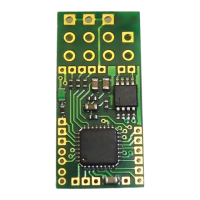
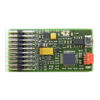
Details on RC connection points and solderpad layout.

Technical Specifications

Key technical data including dimensions, voltage, current, and output power.

Connection Ports Explained

Explanation of various connection pins like LS, PROP, LRN, and Prog.

1. Introduction to Soundmodule TBS Micro V2.0

Configuration Software and Libraries

Information on TBS Flash software and sound libraries for unit configuration.

Overview of Control Modes

Lists the various methods available for controlling the sound unit.

2. Control Modes

2.1. 12-Position Encoder Control

Setup and operation of the sound unit using a 12-position rotary encoder.

Teaching Encoder Control

Step-by-step guide to program the sound unit for encoder control.

2.2. Direct Sound Selection

Using a 3-position switch for selecting specific sounds.

Teaching Direct Sound Selection

Instructions for programming direct sound selection via a 3-position switch.

2.3. Indirect Sound Selection

Using a 3-position switch for indirect selection of multiple sounds.

Teaching Indirect Sound Selection

Steps to program the unit for indirect sound selection using a switch/joystick.

2.4. Autostart Mode

How to configure the sound unit for automatic engine start.

Teaching Autostart Mode

Guide to program the sound unit for autostart mode operation.

2.5. Changing Control Mode

Method to change the programmed control mode without the adapter.

3. USB Programming Cable

Disclaimer

Legal disclaimers regarding product use, liability, and compliance.

Overview

The TBS Micro V2.0 is a compact digital sound unit designed for RC models, suitable for various applications including 1/87 scale models and electric planes due to its small dimensions and light weight. It connects directly to the receiver outputs, in parallel with the speed controller, allowing it to be used with brushless motors. The unit includes a 1W NF amplifier.

Function Description:

The primary function of the TBS Micro V2.0 is to provide realistic sound effects for RC models. It can play engine sounds and various special sounds, which can be triggered and controlled through different modes. The sound unit receives power and control signals from the RC receiver. An optional programming adapter allows for configuration and installation of new sounds from a PC. The volume can be adjusted remotely via the RC transmitter or manually at an external amplifier.

Important Technical Specifications:

  • Dimensions: 11 x 23.5 x 3.2mm (minimum 11x16x3.2mm)
  • Voltage: 3V to max. 5V (supplied by the receiver)
  • Current: Approximately 10mA without sound, approximately 250mA at max. volume
  • Speaker Impedance: 8-32 Ohm
  • Output Power: 1W at 8-Ohm at 5V, 0.6W at 8-Ohm at 3V
  • Proportional Inputs: Positive pulse 0.8ms to 2.0ms
  • Sound Quality: Up to 22.05 kHz
  • Connections:
    • LS (Speaker): Speaker or external amplifier
    • PROP_1: Prop. input for speed controller
    • PROP_2: Prop. input for special functions (configurable)
    • PROP_3: Prop. input for controlling (used for 12-position encoder or two-position toggle switch)
    • LRN: Bridge to enter learn mode
    • Prog: Connector for the optional programming adaptor

Usage Features:

Control Modes: The sound unit supports several control modes, which can be selected using the programming adapter or manually:

  1. 12-Position Encoder: This is the most comprehensive control mode. It uses a 12-position rotary switch with a push button, typically mounted in the transmitter and connected to Prop3. The rotary switch selects the desired sound, and the push button triggers it. The encoder must be ordered separately.

    • Teaching Procedure for Encoder Control:
      1. Power on transmitter and receiver. Bring all joysticks to neutral. LED blinks fast (normal mode).
      2. Bridge LRN contact for ~0.5 seconds until a beep occurs and LED stays on. Neutral/idle positions are stored.
      3. Move throttle stick to the desired acceleration point (where idle dead band stops and engine sound starts) and push the encoder button. A short acceleration sequence plays, defining the dead (neutral) band of the speed channel.
      4. Move throttle stick to full speed position and push the encoder button again. A short full speed sequence plays.
      5. Bring the encoder rotary switch to its first position and push the encoder button. Engine start/stop is stored.
      6. Bring the encoder rotary switch to the next position and push the encoder button. Reeving up the engine is stored.
      7. Repeat step 6 until all 12 rotary switch positions are stored.
      8. The 12th position is usually set to volume control. After programming, the unit beeps 3x and returns to normal operation.
    • Encoder Resistance Adjustment: The total resistance of the encoder can be adjusted by two solder bridges on its PCB:
      • Both bridges open: ~22 KOhm
      • Both bridges closed: ~5 KOhm
  2. Direct Sound Selection by a 3-Position Switch (Toggle Switch): This mode is for running engine sound and one special sound (e.g., MG). It requires a proportional channel with a 3-position switch (neutral position and momentary contacts) or a common joystick channel, connected to Prop2.

    • Teaching Procedure for Direct Sound Selection (similar to Autostart):
      1. Power on transmitter and receiver. Bring throttle stick to idle. LED blinks fast.
      2. Bridge LRN contact for ~0.5 seconds until a beep occurs and LED stays on. Idle position of throttle stick is stored.
      3. Move throttle stick to the desired acceleration point (where idle dead band stops and engine sound starts) and wait for a beep. The dead (neutral) band of the speed channel is defined.
      4. Move throttle stick to full speed position and wait for three beeps. After this, the sound unit returns to normal operation. During programming, if you leave the last stored throttle stick position, a short beep plays, giving ~2 seconds to adjust the new position.
  3. Indirect Sound Selection by a 3-Position Switch (Toggle Switch): This mode allows selection of all sounds using a toggle switch with a neutral position (recommended) or a common joystick on an available proportional channel, connected to Prop3.

    • Selecting a Sound: Push the switch/stick multiple times from its neutral position in one direction to select the desired sound (e.g., 3 pushes for sound #3). The selected sound is triggered by pushing the switch/stick in the other direction. The last selected sound can be triggered multiple times without re-selection.
    • Teaching Procedure for Toggle Switch / Joystick Control:
      1. Power on transmitter and receiver. Bring throttle stick to minimum and control the center position of the toggle switch. LED blinks fast.
      2. Bridge LRN contact for ~0.5 seconds until a beep occurs and LED stays on. All neutral positions are stored.
      3. Move throttle stick to the desired acceleration point and push the switch/joystick of the control channel once. A short acceleration sequence plays, defining the dead (neutral) band of the speed channel.
      4. Move throttle stick to full speed position and push the switch/stick of the control channel again. A short full speed sequence plays. After this, the sound unit returns to normal operation.
  4. Autostart Mode: If only engine sound is desired, this mode can be selected. The engine starts automatically when the model is accelerated for the first time. If the engine idles for more than 20 seconds, it shuts down automatically. No special sounds can be played in this mode.

    • Teaching Procedure for Autostart Mode:
      1. Power on transmitter and receiver. Bring throttle stick to idle. LED blinks fast.
      2. Bridge LRN contact for ~0.5 seconds until a beep occurs and LED stays on. Idle position of throttle stick is stored.
      3. Move throttle stick to the desired acceleration point and wait for a beep. The dead (neutral) band of the speed channel is defined.
      4. Move the throttle stick to full speed position and wait for three beeps. After this, the sound unit returns to normal operation.

Changing Control Mode Manually:

The control mode can be changed without the programming adapter:

  1. Bridge the LRN contact during powering the sound module.
  2. Remove the LRN contact.
  3. Close the LRN contact momentarily and wait for the "Beep-Code."
  4. Repeat closing the LRN contact until the desired control mode is signaled by its corresponding "Beep-Code":
    • 1 x Beep -> Autostart
    • 2 x Beep -> Toggle switch
    • 3 x Beep -> 12-position encoder
  5. Switch the sound module off and on again.

Connections and Installation:

  • Electrical connections to the receiver can be made using common servo cables plugged into sockets on the PCB.
  • For space-critical applications, the PCB area for the sockets can be cut, requiring servo signals and power supply to be soldered directly to copper spots.
  • The TBS Micro is delivered with unmounted sockets, offering flexibility for direct soldering or using sockets.
  • Programming Cable: The optional programming adapter connects to the "Prog" contacts. The brown wire of the programming cable must be connected to the outer (right) side of the PCB. The pins of the USB programming cable may need to be slightly bent for good contact. Do not move the plug during programming.

Maintenance Features:

  • Configuration Software: The free configuration software "TBS Flash" is available at www.benedini.de, along with free sound libraries. This software allows users to configure the sound unit and install new sounds.
  • Firmware Updates: While not explicitly stated as a "maintenance feature," the ability to install new sounds implies that the unit can be updated or customized, which is a form of ongoing maintenance for functionality and content.

Important Notes:

  • Maximum supply voltage is 5V.
  • The installation of the encoder in a transmitter is at the user's own risk, and proper functionality is not guaranteed for all transmitter brands/types.
  • Do not solder wires to the "Prog" contacts if using the optional programming adapter, as these contacts are shared.
  • The manufacturer, Thomas Benedini, provides disclaimers regarding liability for damage caused by non-adherence to instructions, malfunctions outside their control, or improper final assembly.
  • The device is not suited for children.

Benedini TBS Micro V2.0 Specifications

General IconGeneral
BrandBenedini
ModelTBS Micro V2.0
CategoryRecording Equipment
LanguageEnglish

Related product manuals