21
EN
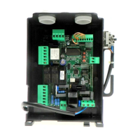
TYPES OF INSTALLATION
AUTOMATIC SYSTEM WITH ENCODER
Start a self-test operation, as indicated in the AUTO Menu.
At completion of the lelf-learning, the value of all torques and the TDMO/TDMC value are preset by the control unit.
If an obstacle is present, the Encoder acts as anti-crash sensor. Its sensitivity is adjusted by SEAV and SEAR parameters.
AUTOMATIC SYSTEM WITH ELECTROMECHANIC LIMIT SWITCHES
In this operating mode, the NOT=ON logics and the ENC=OFF logics must be preset.
All parameters must be preset manually. In particular, values of TM1/TM2 must be some seconds higher than the actual operating time.
AUTOMATIC SYSTEM WITH ELECTROMECHANIC LIMIT SWITCHES AND WITHOUT ENCODER
In this operating mode, the NOT=OFF logics and the ENC=OFF logics must be preset.
All parameters must be preset manually. In particular, values of TM1/TM2 must be some seconds higher than the actual operating time.
ERROR MESAGES
Some messages that are displayed in the event of malfunctions are shown hereunder:
Enc1
Error, motor 1 encoder Check the connection to motor 1 encoder
Enc2
Error, motor 2 encoder Check the connection to motor 2 encoder
Amp1
Error, motor 1 obstacle Check the presence of obstacles on the motor 1 leaf stroke
Amp2
Error, motor 2 obstacle Check the presence of obstacles on the motor 2 leaf stroke
Err1
Error, check motor 1 circuit Check connections to motor 1
Err2
Error, check motor 2 circuit Check connections to motor 2
Err3
Error, check actiation relay Ask for technical assistance
Err4
Error, check PHOTA photocell Check connections, alignment of PHOT A photocell or obstacle present.
Err5
Error, check PHOTC photocell Check connections, alignment of PHOT C photocell or obstacle present.
Err6
Error, activated sensitive edge (during self-set) During self-setting, the safety edge was activated.
Err7
Error, activated stop (during self-test) During self-setting, the STOP input was activated.
Err8
Error, activated input (during self-test) During self-setting, a Start/Pedestrian/Open/Close input was activated.
DIAGNOSTICS
In the event of malfunctions, by pressing key + or - the status of all inputs (limit switches,
control and safety) can be displayed. One segment of the display is linked to each input.
In the event of failure it switches on according to the following scheme.
PHOT-O
SWC-M1
STOP
SWO-M1 SWO-M2
SWC-M2
PHOT-C
DAS
P.P. PED OPEN CLOSE
TECHNICAL DATA
Mains power supply
230 Vac ±10% 50/60 Hz (120 Vac ±10%50/60 Hz for BRAINY 115)
Output, Motor
1/2 motor, 230 Vac ±10%(1/2 motors 120 Vac ±10%for BRAINY 115)
Motor maximum power
600W + 600W
Output, power supply of accessories
24VAC 1A max.
Protection level
IP54
Operating temperature
-20°C / +60°C
Radio receiver
433,92 MHz, incorporated and configurable
No. of codes storable in memory
64