BRAINY
Full feature control panel
USE THIS QUICK START GUIDE TOGETHER
WITH THE INSTRUCTION MANUAL PROVIDED.
QUICK START GUIDE
STAGE 1:
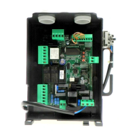
First stage is to correctly wire in the motors
to the panel via terminals 4, 5 & 6 for Motor
1 and 7, 8 & 9 for Motor 2 . If only
using a single operator, ensure to just use
the motor 1 terminals 4,5, & 6 and turn
to ON in the logic menu.
Most of the parameters can be pre-
determined via the autoset feature.
This can only be used when using
motors equipped with encoders.
If installing motors without encoders
then set up of the panel must be
completed manually. To do this, you
must ensure that the LOGIC setting
ENC is turned OFF.
Beninca Automation UK Ltd
Unit 4, Plenty Close,
Newbury, Berkshire, RG14 5RL
beninca.co.uk
01488 658 276
info@beninca.co.uk
beninca.co.uk
QSG B R A INY_ 07_19
F2
F1
GND
STOP
PHOT (Close)
PHOT
CLOSE
OPEN
PED.
P. P.
COM
COM
SWC-M2 (Close)
SWO-M2 (Open)
SWC-M1 (Close)
SWO-M1 (Open)
L N
115/230Vac
50/60Hz
J2 DAS
Close
DAS 8K2
J2 DAS
Open
DAS N.C.
AUX 1
AUX 2
STAGE 2:
Power up the control. At this point, you
should have only the motors wired in.
Press the < - > button to trigger the gates.
Both gates should attempt to open. If
either begins to close upon triggering you
will need to reverse the phases of that
particular motor.
Note; the DL4 light will constantly flash.
This is perfectly normal.
A
B
NAVIGATING THE PANEL
BUTTONS:
+ Navigate up / Increase value
OK Enter / Select / Confirm
- Navigate down / Decrease value /
Trigger
UNDERSTANDING
THE BASIC MENUS
PARAMETERS
(
PAr
)
All settings with
numerical values that can be altered.
Time, force, percentages.
LOGIC
(
LOG
)
All settings that can be
turned on or off.
RADIO
(
RAD
)
All settings relating to
adding or removing transmitters.
Autoset (Auto) Self calibration setting
of encoded motors.
+ Brown
S Green
- White
1. 2.
STAGE 2:
Power up the control. At this point,
you should have only the motors
wired in.
Press the < - > button to trigger the
gates. Both gates should attempt to
open. If either begins to close upon
triggering you will need to reverse the
phases of that particular motor.
Note; the DL4 light will constantly
flash. This is perfectly normal.
STAGE 1:
First stage is to correctly wire in the
motors to the panel via terminals
4, 5 & 6 for Motor 1 A and 7, 8 & 9
for Motor 2 B . If only using a single
operator, ensure to just use the motor
1 terminals 4,5, & 6 and turn Inot to
ON in the logic menu.
Most of the parameters can
be pre-determined via the
autoset feature. This can
only be used when using motors
equipped with encoders.
If installing motors without
encoders then set up of the panel
must be completed manually. To
do this, you must ensure that the
LOGIC setting Enc is turned OFF.
NAVIGATING THE PANEL
BUTTONS:
+ Navigate up / Increase value
OK Enter / Select / Confirm
- Navigate down / Decrease
value / Trigger
UNDERSTANDING
THE BASIC MENUS
PARAMETERS
(
PAr
)
All settings
with numerical values that can be
altered. Time, force, percentages.
LOGIC
(
LOG
)
All settings that can
be turned on or off.
RADIO
(
RAD
)
All settings relating to
adding or removing transmitters.
Autoset
(
AUto
)
Self calibration
setting of encoded motors.
BRAINY
Full feature control panel
USE THIS QUICK START GUIDE TOGETHER
WITH THE INSTRUCTION MANUAL PROVIDED.
QUICK START GUIDE
STAGE 1:
First stage is to correctly wire in the motors
to the panel via terminals 4, 5 & 6 for Motor
1 and 7, 8 & 9 for Motor 2 . If only
using a single operator, ensure to just use
the motor 1 terminals 4,5, & 6 and turn
to ON in the logic menu.
Most of the parameters can be pre-
determined via the autoset feature.
This can only be used when using
motors equipped with encoders.
If installing motors without encoders
then set up of the panel must be
completed manually. To do this, you
must ensure that the LOGIC setting
ENC is turned OFF.
Beninca Automation UK Ltd
Unit 4, Plenty Close,
Newbury, Berkshire, RG14 5RL
beninca.co.uk
01488 658 276
info@beninca.co.uk
beninca.co.uk
QSG B R A I NY_ 07_19
F2
F1
GND
STOP
PHOT (Close)
PHOT
CLOSE
OPEN
PED.
P. P.
COM
COM
SWC-M2 (Close)
SWO-M2 (Open)
SWC-M1 (Close)
SWO-M1 (Open)
L N
115/230Vac
50/60Hz
J2 DAS
Close
DAS 8K2
J2 DAS
Open
DAS N.C.
AUX 1
AUX 2
STAGE 2:
Power up the control. At this point, you
should have only the motors wired in.
Press the < - > button to trigger the gates.
Both gates should attempt to open. If
either begins to close upon triggering you
will need to reverse the phases of that
particular motor.
Note; the DL4 light will constantly flash.
This is perfectly normal.
A
A B
B
NAVIGATING THE PANEL
BUTTONS:
+ Navigate up / Increase value
OK Enter / Select / Confirm
- Navigate down / Decrease value /
Trigger
UNDERSTANDING
THE BASIC MENUS
PARAMETERS
(
PAr
)
All settings with
numerical values that can be altered.
Time, force, percentages.
LOGIC
(
LOG
)
All settings that can be
turned on or off.
RADIO
(
RAD
)
All settings relating to
adding or removing transmitters.
Autoset (Auto) Self calibration setting
of encoded motors.
+ Brown
S Green
- White
!!
UNITED
KINGDOM
QUICK START GUIDE
BRAINY
Full feature control panel
USE THIS QUICK START GUIDE TOGETHER
WITH THE INSTRUCTION MANUAL PROVIDED.
01488 658 276
info@beninca.co.uk
beninca.co.uk