The CP.BISON OTI is a control unit designed for a single motor, ideal for sliding doors. It is manufactured by AUTOMATISMI BENINCÀ SPA. This device complies with EU Directives 2004/108/CE (EMC) and 2006/95/CE (LVD), adhering to harmonized standards such as EN 61000-6-2:2005, EN 61000-6-3:2007, EN 60335-1:2002, EN 60335-1-103:2003, and, where applicable, Directive 1999/5/CE, including ETSI EN 301 489-3 V1.4.1 (2002), ETSI EN 301 489-1 V1.4.1 (2002), ETSI EN 300 220-3 V1.1.1 (2000), and EN 60950-1 (2001).
Function Description
The CP.BISON OTI control unit manages the operation of a single motor for sliding doors, integrating an embedded anti-crash device (amperometric sensor). However, due to the overall dimensions of the door leaves, this sensor is not considered a primary safety device, making the installation of activated protection sensitive edges strictly mandatory in accordance with regulations.
The unit supports both single-phase (230 VAC 50/60 Hz for BISON 25 OTI) and three-phase (400 VAC 50/60 Hz for BISON 30/45 OTI) mains power supply. It controls one motor, which can be either 230 V three-phase or 400 VAC three-phase. The motor maximum current is 8A for BISON 25 OTI and 2.6A for BISON 40 OTI. It provides a 24VAC 0.4A max output for accessories.
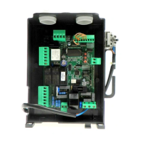
The control unit features various inputs and outputs for comprehensive control:
- Power Supply (1-2-3-4): Connects to single-phase or three-phase mains. Includes a mains filter.
- INVERTER (5-6-7-8): Connects to the single-phase or three-phase inverter.
- Flashing Light (9-10): Connects to a 230VAC 40W max or 115VAC 40W max flashing light for BISON TI 115.
- 24V Flashing Light or Phototest (15-16): Connects to a 24VAC flashing light or phototest output for checked photocells.
- SCA (17-18): Normally open, voltage-free contact for an open gate indicator light (24VAC 0.5A max).
- 24 VAC (19-20): Output for accessory power supply (24Vac/400mA max).
- SERIAL 485 (Serial, Inverter): 485 serial communication between control logics and Inverter.
- Encoder: Connection to the motor Encoder.
- Antenna (21-22): Connection to the built-in radio receiver module (21-signal/22-monitor).
- COM (23-36): Common for all control inputs.
- SWC (24): Input for CLOSE limit switch (Normally Closed contact).
- SWO (25): Input for OPEN limit switch (Normally Closed contact).
- PHOT 1-4 (26-29): Inputs for Limit switches 1-4 (NC contact). These can be disconnected in the opening phase based on PH01-PH04 logics.
- STOP (30): Input for STOP push-button (Normally Closed contact).
- OPEN (31): Input for OPEN contact push-button (Normally Open contact).
- CLOSE (32): Input for CLOSE push-button (Normally Open contact).
- PED (33): Input for pedestrian opening push-button (Normally Open contact).
- Step-by-Step (34): Input for Step-by-Step push-button (Normally Open contact).
- AUX IN (35): Input for Dead man function (enabled by connecting to 36-COM). Used with an appropriately marked N.O. contact for automation control even if the encoder fails.
- N/A (35): Not in use.
- SAFETY (37-38): Input for sensitive safety edge. Stops door movement when activated. Jumper "DAS" closed for resistive type, open for mechanical type.
- INVERTER (39-40): Safety connection for hardware emergency stop to the inverter. Always open with stopped motor, pressed SAFETY push-button, or open motor removable side in BULL 40 OTL.
- COVER (41-42): Safety switch, pre-wired to the micro-switch on the removable front side of the automatic system. Blocks operations when the cover is opened.
- SAFETY (43-44): Optional safety switch for self-locking emergency push-button. Short-circuited if not in use.
- AUX-OUT (45-46): Auxiliary output, configurable via AUX parameter. Voltage-free contact, 250VAC 16A max.
- VOLTAGE SELECTOR (47-48-49): Selects power supply voltage (47 and 48 for single-phase 230VAC; 48 and 49 for three-phase 400VAC). For motors with thermal switch, activation opens contact and cuts power to the board.
Important Technical Specifications
- Mains Power Supply: Single-phase: 230 VAC 50/60 Hz (BISON 25 OTI); Three-phase: 400 VAC 50/60 Hz (BISON 30/45 OTI).
- Motor Output: 1 motor, 230 V three-phase or 400 VAC three-phase.
- Motor Max Current: BISON 25 OTI: 8A; BISON 40 OTI: 2.6A.
- Output, Power Supply of Accessories: 24VAC 0.4A max.
- Protection Level: IP54.
- Operating Temperature: -20°C / +50°C.
- Radio Receiver: 433.92 MHz, incorporated and configurable (rolling-code or fixed+rolling-code+ ARC Advanced Rolling Code).
- No. of Codes Storable in Memory: 64.
- Fuses:
- F1: 250V T1A (Protection, power supply of accessories).
- F2: 250V T400mA (Protection, logics of board).
- F3: 250V T630mA (Protection, common inputs and serial of inverter).
- F4: 500V T125mA (Protection, transformer primary).
- F5: 250V T500mA (Protection, flashing light, 230V).
Usage Features
The CP.BISON OTI control unit offers extensive programming capabilities via its LCD display, allowing users to adjust various functions and parameters.
- Programming Access:
- Press to enter the "Parameters" menu ("PAR").
- Use <+> or <-> to select the desired menu.
- Press to view the first function.
- Use <+> or <-> to select the desired function.
- Press to view the current value.
- Use <+> or <-> to select the new value.
- Press to confirm, indicated by "PRG".
- Parameters (PAr) include:
- tCA (Automatic closure time): 1-240s (default 40s). Activated with "TCA" logics:ON.
- tPED (Pedestrian opening percentage): 5-100% (default 20%).
- tSN (Braking during opening/closure): 10-100% (default 20%).
- tOP (Motor operating time): 5-240s (default 240s). Effective only if ENC logics is OFF.
- FStS (Opening/closing speed): 20-90 (default 45). Important: Change values only according to weight limits in Table 1.
- SLdS (Speed during braking): 10-40 (default 25).
- Pno (Torque motor 2 opening): 1-99% (default 70%).
- Pnc (Torque motor 2 closing): 1-99% (default 70%).
- SErO (Anti-crash device trigger time - normal speed): 0-90% (default 0%). 0:Off-90:max sensibility-1:min sensibility.
- SEAr (Anti-crash device trigger time - braking phase): 0-90% (default 0%).
- bLc (Stop space after limit switch): 1-10cm (default 3cm).
- tLS (Service light activation time): 1-240s (default 60s). Activated with AUX 1 parameter preset to value 2.
- tAcc (Ramp during acceleration): 1-25 (default 20) in tenths of seconds.
- tDEC (Ramp during deceleration): 50-99 (default 50) in tenths of seconds.
- tbr (Emergency braking): 1-20 (default 3) in tenths of seconds.
- SP In (Reversal space after safety edge): 1-4 (default 2). 1: ~20cm, 4: ~60cm.
- AUH (AUX output mode): 1-3 (default 1). 1: Second radio channel; 2: Service light; 3: Area light.
- Logic (LoG) settings include:
- tCA (Automatic closing): ON/OFF (default OFF).
- tbL (Multi-flat function): ON/OFF (default OFF).
- tbCA (PP controls during TCA): ON/OFF (default OFF).
- ScL (Rapid closure): ON/OFF (default OFF).
- PP (P.P. Push button mode): ON/OFF (default OFF). ON: OPEN > CLOSE > OPEN; OFF: OPEN > STOP > CLOSE > STOP.
- PrE (Forewarning flashing light): ON/OFF (default OFF).
- htr (Service Man function): ON/OFF (default OFF).
- tLCA (Blinker during TCA): ON/OFF (default OFF).
- Enc (Encoder): ON/OFF (default ON).
- Pho1-4 (PHOT 1-4 input): ON/OFF (default OFF). ON: Photocell activated only in closing phase; OFF: Photocell activated in both opening and closing phases.
- tSt1-4 (Photocell check): ON/OFF (default OFF).
- tInU (Motor opening direction): ON/OFF (default OFF). ON: Right side motor mount; OFF: Left side motor mount.
- Radio (rAd) functions:
- PP (Step-by-step transmitter learning): Assigns a transmitter code to the step-by-step function.
- 2ch (Second radio channel learning): Assigns a transmitter code to the second radio channel.
- PEd (PED function learning): Assigns a transmitter code to the PED function.
- CLr (Erase transmitter code): Erases a transmitter code from memory.
- rSt (Erase all memory): Erases all transmitter codes.
- Password (codE): Allows setting a 4-character alphanumeric access code (default 0000) to protect programming.
- Stroke Self-Learning (AutO): The system automatically learns the door/gate stroke. This is crucial for correct braking operation.
- Remote Learning: Transmitters can be learned remotely if a code is already stored and REM logics are ON.
- Press the hidden key of the stored transmitter.
- Within 5 seconds, press the stored transmitter key for the channel to be matched. Flashing light switches on.
- Within 10 seconds, press the hidden key of the new transmitter.
- Within 5 seconds, press the new transmitter key for the selected channel. Flashing light switches off.
- The receiver stores the new code and exits programming.
Maintenance Features
- Maintenance Indicator (MAn t): Allows setting a number of operations (in hundreds of cycles, e.g., 50 means 5000 operations) after which maintenance is required. The flashing light will blink for ~10 seconds at the end of an operation to indicate maintenance is needed.
- Reset (rES): Resets the control unit to default values. Transmitter codes and gate leaf position/stroke are not erased.
- Diagnostics: The LCD display can show the status of all inputs (limit switches, control, safety) by pressing <+> or <->. Each segment of the display is linked to an input, and it switches on if there is a failure.
- Error Messages: The control unit displays error codes to aid in troubleshooting:
- Err: Self-calibration error (check inputs, frictions).
- Err1: Inverter/Cover/Safety error (check safety contact, cover contact, inverter).
- Err2: Photocell autotest error (check photocells).
- Err3: Encoder error (check encoder connections).
- Err4: Sensitive edge error (check sensitive edge connections).
- Err5: Phototest error (check photocell connections).
- Econ: Inverter communication error (check 485 serial connections).
- AnP: Amperometric sensor triggering (remove obstacle, check door stroke).
- F 00 - F 15: Inverter error/alarm (contact technical assistance).
- Waste Disposal: If the product needs to be dismantled, it must be disposed of according to regulations for differentiated waste disposal and recycling of components (metals, plastics, electric cables, etc.). It is advisable to contact an installer or specialized company for this operation.
Important Notes for Installers:
- This manual is intended for qualified fitters only.
- Ensure an omnipolar switch or selector with a contact distance of 3mm or more is installed on the supply net.
- Verify the electrical system has a differential interrupter and overcurrent protection.
- Some installations may require connecting the shutter to a conductive ground mass.
- Electrical installation and operating logic must comply with regulations.
- Leads with different voltages must be physically separate or insulated with at least 1mm additional insulation.
- Secure leads with an additional fixture near terminals.
- Interrupt power supply before opening the lid for electrical work.
- Check all connections before powering on.
- Unused N.C. inputs must be bridged.
- The anti-crash device is disabled by default. The use of activated safety sensitive edges is mandatory.
- If FSTS and SLDS parameters are changed, SEAV and SEAR parameters are automatically set to 0.
- If the FSTS speed is increased, TSM, TACC, and TDEC values must be proportionally increased to avoid mechanical stress.
- A short TSM value combined with a high TDEC value can cancel the SLDS braking phase.
- If the encoder is disabled, stroke self-learning cannot be carried out, and a new complete operation is required to reset braking after power failure or manual operation.
- The LCD display can be rotated 180° for convenience.