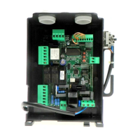
CP.BISON OTI CONTROL UNIT
INPUT/OUTPUT FUNCTIONS
CAUTION!: The CP.BISON OTI control unit is equipped with an embedded anti-crash device (amperometric
sensor). Given the overall dimensions of the door leaves for which the device is intended, the latter cannot
be considered a safety device. It is therefore STRICTRLY MANDATORY to install activated protection sen-
sitive edges according to regulations in force.
N° Terminals Function Description
1-2-3-4 Power supply
Single-phase or three-phase mains power supply.
The unit is powered through a mains filter applied before the control unit.
Single-phase 1: Phase - 2: Neutral – 3: Not in use - 4: GND
Three-phase 1:L1 - 2:L2 - 3:L3 - 4:GND.
5-6-7-8 INVERTER
Single-phase or three-phase INVERTER connection
Single-phase 6: Phase – 7: NEUTRAL
Three-phase 5:GND - 6:R - 7:S - 8:T.
9-10 Flashing light Connection of flashing light, 230VAC 40W max, or 115VAC 40W max, for BISON TI 115.
15-16
24V Flashing
light or Phototest
Connection to 24VAC flashing light or Phototest output for checked photocells.
17-18 SCA Normally open, voltage-fee contact for open gate indicator light, 24VAC 0.5A max
19-20 24 VAC Output, power supply of accessories, 24Vac/400mA max
SERIAL 485 Serial, inverter 485 serial communication between control logics and Inverter.
Encoder Encoder Connection to motor Encoder.
21-22 Antenna Connection to built-in radio receiver module of the antenna (21-signal/22-monitor).
23-36 COM Common, for all control inputs.
24 SWC Input, CLOSE limit switch (Normally Closed contact)
25 SWO Input, OPEN limit switch (Normally Closed contact)
26 PHOT 1
Input, Limit switch 1 (NC contact). It can be disconnected in the opening phase, see PH01 logics.
27 PHOT 2
Input, Limit switch 2 (NC contact). It can be disconnected in the opening phase, see PH02 logics.
28 PHOT 3
Input, Limit switch 3 (NC contact). It can be disconnected in the opening phase, see PH03 logics.
29 PHOT 4
Input, Limit switch 4(NC contact). It can be disconnected in the opening phase, see PH04 logics.
30 STOP Input, STOP push-button (Normally Closed contact)
31 OPEN Input, push-button for OPEN contact (Normally Open contact)
32 CLOSE Input, CLOSE push-button (Normally Open contact)
33 PED Input, push-button for pedestrian opening (Normally Open contact)
34 Step-by-Step Input, Step-by-Step push-button (Normally Open contact)
35 AUX IN
Input for Dead man function
By connecting this output to 36-COM terminal, dead man function is enabled.
To be used by means an appropriately marked N.O. contact for controlling the automation
even in case of encoder failure.
35 N/A Not in use
37-38 SAFETY
Input, sensitive safety edge.
When the safety edge is activated, the door movement is stopped
and reversed (see SPIN Parametters).
Safety edge of the resistive type: Jumper “DAS” closed.
Safety edge of the mechanical type: Jumper “DAS” open.
TECHNICAL DATA
Mains power supply
Single-phase: (BISON 25 OTI) 230 VAC 50/60 Hz
Three-phase: (BISON 30/45 OTI) 400 VAC 50/60 Hz
Output, Motor
1 motor, 230 V three-phase or 400 VAC three-phase
Motor max current
BISON 25 OTI: 8A - BISON 40 OTI 2.6 A
Output, power supply of accessories
24VAC 0.4 A max.
Protection level
IP54
Operating temperature
-20°C / +50°C
Radio receiver
433,92 MHz, incorporated and configurable
(rolling-code or fixed+rolling-code+ ARC Advanced Rolling Code)
No. of codes storable in memory
64
 Loading...