15
EN
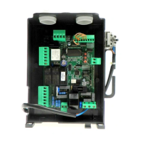
BRAINY CONTROL UNIT
INPUT/OUTPUT FUNCTIONS
N° Terminals Function Description
1-2-3 Power supply Input 230 Vac ±10% 50/60Hz (1-GND/2-Phase/3-Neutral)
4-5-6 Motor 1 Connection of motor 1: (4-start/5-Com/6-start)
7-8-9 Motor 2 Connection of motor 2: (7-start/8-Com/9-start)
10-11 Blinking light Connection of blinking light 230Vac 40W max.
12-13 TLS
N.O. clean contact (230V/16A max) for courtesy light, timer, etc.
The activation time is regulated by the parameter TLS
14-15 24 Vac Accessories power supply output 24Vac/1A max.
16-17 Lock 12Vdc Accessories power supply output 12Vac/10W for electric lock (16:0V, 17:+12V)
18-19 AUX1 Normally Open clean contact, configurable as SCA- open gate light (default) or photocell test.
20-21 EDGE
Input, sensitive edge contact
Resistive edge: “DAS” Jumper closed
Mechanical edge: “DAS” Jumper open
When the edge is activated, the gate movement is stopped and reversed for about 3s.
22 SWO-M1 OPEN limit switch input motor 1 (N.C contact.)
23 SWC-M1 CLOSE limit switch input motor 1 (N.C. contact)
24 SWO-M2 OPEN limit switch input motor 2 (N.C. contact)
25 SWC-M2 CLOSE limit switch input motor 2 (N.C. contact)
26-27 COM Common for limit switch and all the control inputs.
28 Step-by-Step Step-by-Step button input (N.O. contact)
29 PED Pedestrian button input (N.O. contact)
30 OPEN
Input, OPEN push-button (Normally open contact).
It is possible to connect a timer for opening in time slots.
31 CLOSE CLOSE button input (N.O. contact)
32 PHOT Active photocell input on opening and closing
33 PHOT CLOSE Active photocell input only on closing
34 STOP STOP button input (N.C. contact)
35-36 Antenna
Antenna connection for plug-in radio receiver board (35-screen/36-signal).
37-38 AUX2
Voltage-free Normally Open Contact. Configurable as second radio channel (default) or SCA-
open gate LED.
J3 Radio Plug-in connector for radio receiver.
The control unit is equipped with an built-in radio module for the reception of variable code controls, with ARC (Advanced Rolling-
Code) or fixed code, 433.92 MHz frequency.
NOTES
The EDGE must be connected exclusively to the special inputs 20/21. Two types of EDGE may be used:
If an edge with resistance 8K2 is used, close the Jumper “DAS”.
If a mechanical edge with N.C. contact is used, open the Jumper “DAS”.
If the edge is not used, bridge the terminals 20-21 and open the Jumper “DAS”.
TO CHECK CONNECTIONS:
1) Cut-off power supply.
2) Manually release the wings, move them to approx. half-stroke and lock them again.
3) Reset power supply.
4) Send a step-by-step control signal by pressing the button or the remote control key.
5) The wings should start an opening movement.
If this is not the case, invert the movement wires of the motor. (4<>6 for motor M1, and 7<>9 for motor M2) and the relevant limit
switch inputs (22<>23 for motor M1, and 24<>25 for motor M2).
ARC COMPATIBLE CONTROL UNIT
IMPORTANT, PLEASE READ CAREFULLY:
The radio receiver in this product is compatible with the new ARC (Advanced Rolling Code) transmitters which, thanks to 128-bit en-
cryption ensure superior copy-security.
Storing new ARC transmitters is quite similar to that of normal rolling code transmitters with HCS coding, but be aware that:
1) ARC transmitters and Rolling Code HCS can not be stored in a single receiver.
2) The first transmitter memorized determines the type of transmitters to be used later. If the first transmitter memorized is ARC, you can
not store Rolling code HCS transmitters, and vice versa.