12
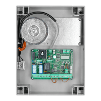
CP.BEN CONTROL UNIT
WIRE DIAGRAM
Wire connections shown in Fig. 1 are described hereunder:
Terminal
no.
Function Description
1-2 24Vac/dc Input, power supply, 24Vac/24Vdc.
3-4 Antenna Connection to insertable radio-receiver card antenna (3-screen/4-signal).
9-10 SCA/SRL/2° Ch
Radio
Volt-free contact, Normally Open, controlled by logics “2° Ch Radio” (2
nd
Radio channel)
and “SRL”.
With “2
nd
Radio channel” logics On: active output as 2
nd
Radio channel.
With “2
nd
Radio channel” logics Off:
- With “SRL” logics On: Contact for courtesy light control
- With “SRL” logics Off: Contact for “SCA” open gate light
11-12 24 Vdc Output, accessories power supply, 24Vc/0.5A max (12+/11-).
13-14 Flashing light Connection of warning flashing light, 24Vdc 15W max.
17 PED/CLOSE With “OPEN/CLOSE” logics Off: Input, pedestrian push-button (Normally Open contact). It
controls motor 1 opening.
With “OPEN/CLOSE” logics On: Input, close push-button (Normally Open contact). It
controls both motors.
18 Step-by-Step/OPEN With “OPEN/CLOSE” logics Off: Input, step-by-step push-button (Normally Open contact).
With “OPEN/CLOSE” logics On: Input, OPEN push-button (Normally Open contact). It
controls the opening of both motors.
19 PHOT C Input, photocell is activated only during closure (Normally Closed contact Normally Closed
contact)
20 PHOT Input, photocell is activated during opening and closing (Normally Closed contact)
21 STOP Input, STOP push-button (Normally Closed contact)
22 COM Common for all control inputs.
23-25 Motor 1 Pre-wired rapid connector, motor 1
24 Motor 1, Ground Ground of motor 1
26-28 Motor 2 Extractable connector for connection of motor 2: 24Vdc 120W max
27 Motor 2, Ground Ground of motor 2
BN.CB Buffer battery Rapid connector for connection of battery charger card BN.CB
TO CHECK CONNECTIONS
1) Cut off power supply.
2) Manually release the gate leaves, move them to around half their stroke and block them again.
3) Restore power supply.
4) Send a sep-by-step control by using the push-button connected to the Input, Step-by-Step (PP), radio control or push-button <->.
TECHNICAL DATA
Contol unit supply
24 Vdc
Power supply
230 Vac 50/60 Hz or 115Vac 50/60Hz according to the version
Output supply
1/2 motor 24Vdc
Power maximum motor
120/120 W
Output supply accessories
24Vdc 500mA max.
Protection level
IP44
Operating temp.
-20°C / +50°C
Radio receiver
built in 433,92 MHz confgurabile (rolling-code or programmable + rolling-code)
Rolling code transmitters supported
64

 Loading...