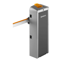
13) CP.EVA2 CONTROL UNIT
13.1) WIRE DIAGRAM
Wire connections shown in Fig. 13 are described hereunder:
TERMINAL BLOCK M3
TERMINALS Function Description
ANT-SHIELD Antenna
Connection for the antenna of the built in receiver (ANT-signal/SHIELD-shield).
In case of use of an external antenna it is necessary to remove the pre-cabled cable from the terminal ANT
AUX Auxiliary output AUX 1 Output with N.O. contact configurable by means of the logic AUX 1
24V 24 Vdc Accessory power supply 24Vdc 500 mA maximum
MOT Motor Motor connection: 24Vdc.
TERMINAL BLOCK M2
P.P. Step by step Input for step by step command (N.O. contact) .
CLOSE Close Input for close command (N.O. contact) .
OPEN Open Input for open command (N.O. contact), It is possible to connect a timer for programmed openings.
PHOT Photocell Input for photocells enabled during opening and closing phase (N.C. contact).
STOP STOP Input for STOP command (N.C. contact).
SWC Closing limit switch
Input for closing limit switch (N.C. contact).
To be used ONLY FOR BARRIER WITH ELECTROMECHANICAL LIMIT SWITCHES. If not used it is NOT
NECESSARY TO BRIDGE the input to the common COM.
SWO Opening limit switch
Input for opening limit switch (N.C. contact).
To be used ONLY FOR BARRIER WITH ELECTROMECHANICAL LIMIT SWITCHES. If not used it is NOT
NECESSARY TO BRIDGE the input to the common COM.
COM Common Common for all the input commands and the limit switches .
AUX2 24Vdc output for bar light
24Vdc output for the bar flashing light EVA.L (max 2), the flashing mode can be set by means of the
logic LBAR.
BLINK Blinker
Output 24Vdc 15W max. for flashing light connection (EVA.LAMP) to be installed on the top cover of the barrier.
TERMINAL BLOCK MENC
ABS ENC Encoder input Absolute encoder input, pre-cabled by factory.
TERMINAL BLOCK M1
M1 24Vdc INPUT
24Vdc input for powering the CP.EVA2.In case of use of the SUN SYSTEM it is necessary to connect
the 24Vdc output of the SUN.SY to M1 (see the KSUN instructions)
13.2) PROGRAMMING
The programming of the various functions of the control unit is carried out using the LCD display on the control unit and setting the desired values in
the programming menus described below.
The parameters menu allows you to assign a numerical value to a function, in the same way as a regulating trimmer.
The logic menu allows you to activate or deactivate a function, in the same way as setting a dip-switch.
13.2.1) TO ACCESS PROGRAMMING
1 -Press the <PG> button to enter the first Installation menu “INST”.
2 -Choose with <+> or <-> button the menu you want to select
3 - Press the button <PG>, the display shows the first function available on the menu.
4 - With the <+> or <-> button, select the function you want.
5 - Press the button <PG>, the display shows the value currently set for the function selected.
6 - With the <+> or <-> button, select the value you intend to assign to the function.
7 - Press the button <PG>, the display shows the signal “PRG” which indicates that programming has been completed.
13.2.2) PROGRAMMING NOTES
Simultaneously pressing <+> and <-> from inside a function menu allows you to return to the previous menu without making any changes. Hold down
the <+> key or the <-> key to accelerate the increase/decrease of the values.
Hold down the <+> key or the <-> key to accelerate the increase/decrease of the values.
After waiting 120s the control unit quits programming mode and switches off the display.
When the board is switched on, the software version is displayed for around 5 sec
The pre-set logic functions and parameters are made taking account of a typical installation.
13.3) PARAMETERS, LOGICS AND SPECIAL FUNCTIONS
The following tables describe the functions available on the control unit
13.3.1) INSTALLATION (INST)
MENU FUNCTION MIN-MAX-(Default) MEMO
BOOM
Select the length of the boom installed on the barrier.
Value expressed in meter from 3m to 5m (EVA5) or from 7m to 8m (EVA8)
According to the selected boom length, the optimal value of speed will be set.
3/5 -7/8 (7-8)
Pos
Set the closing direction of the barrier (see fig. 2)
The symbol 0--- indicates right barrier (R/RIGHT) DEFAULT
The symbol ---0 indicates left barrier (L/LEFT)
Verify the opening direction of the boom and in case reverse it. Every change of this func-
tion automatically implies the starting of a new AUTOSET procedure.
0--- = RIGHT
---0 = LEFT
( RIGHT )