14
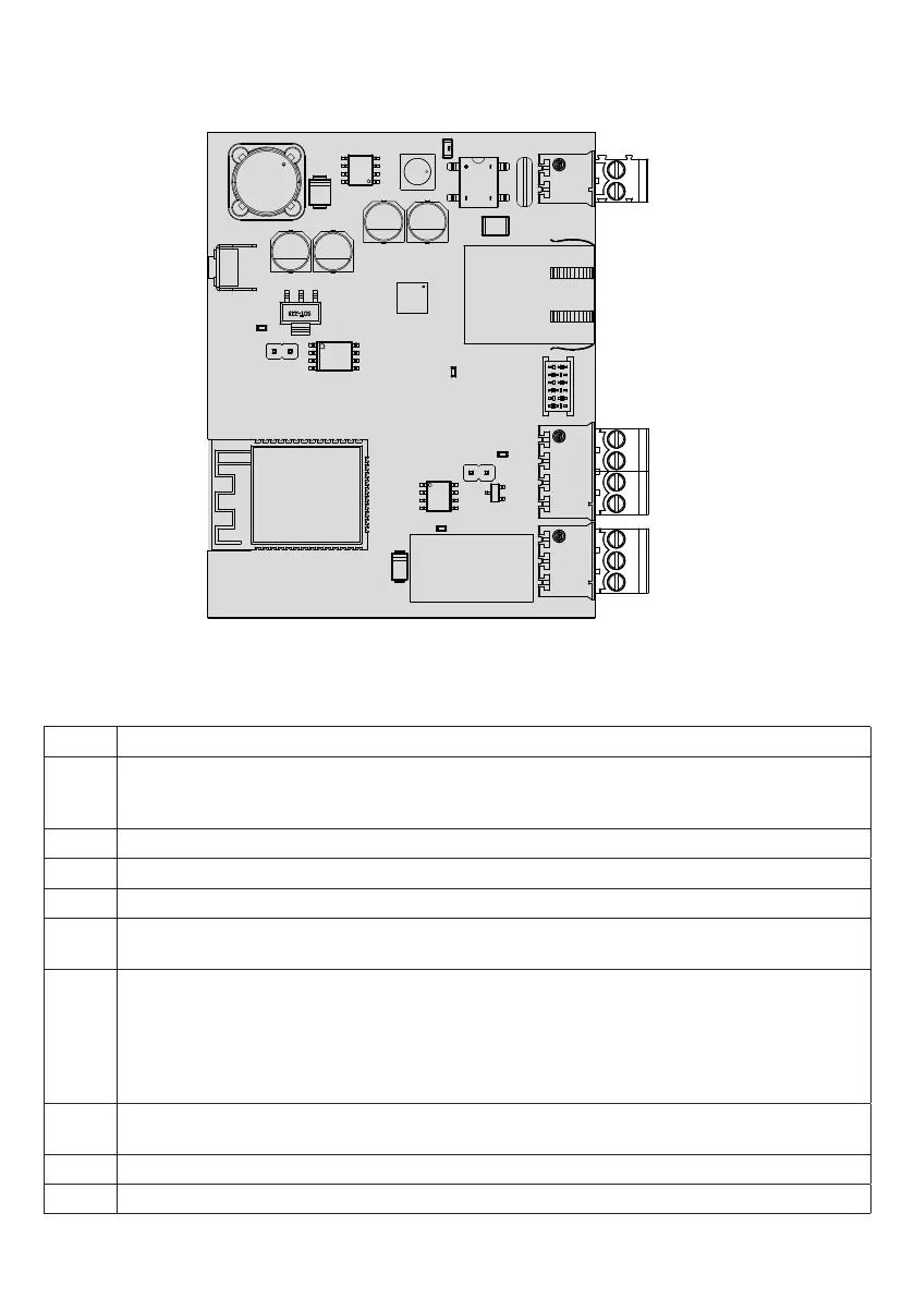
pro.UP board
OUT
IN
EXP
ETH
12/24V
P1
L1
L2
L3
L4
P1 Button to manage the WiFi access point and reset the device
12/24V 12/24 Vac/dc power supply input.
Normally, pro.UP receives power from the EXP connector. In some cases, it may be necessary to directly power the
board.
ETH Ethernet Port
EXP Connector for serial connection to the control unit using the flat cable supplied.
IN Clean contact input
OUT Output equipped with exchange contact NO-NC-COM. to control the external devices (Lights, alarms, etc.)
250Vac 5A max.
L1 LED WiFi /LAN (green colour only):
1) pro.UP not configured (wifi not enabled): LED off.
2) Access Point mode enabled: off 1 second, on 1 second.
3) pro.UP in connection to WiFi/LAN network: off 250 ms, on 250 ms.
4) pro.UP in connection to server via internet: off 125 ms, on 125 ms.
5) pro.UP connected to server: LED always on.
L2 POWER LED (red colour only):
the LED switches on with the light fixed when pro.UP is powered correctly.
L3 Input status diagnostic LED
L4 Output status diagnostic LED
 Loading...