15
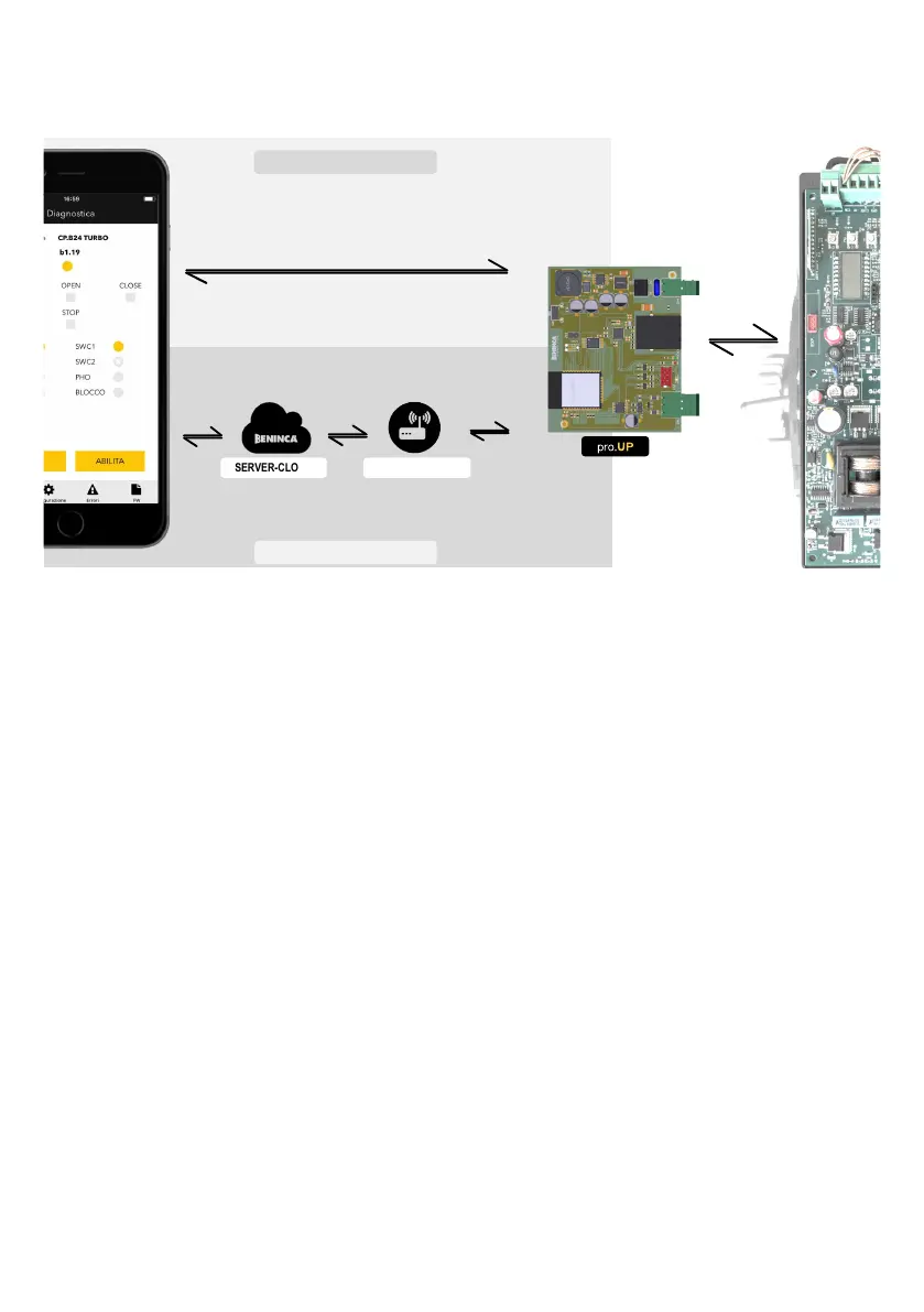
COMMUNICATION SYSTEM OVERVIEW
The connection between pro.UP and the control unit takes place via a flat cable with quick serial connector to the EXP port on the
control unit.
The connection between pro.UP and the BeUP app can take place in two ways:
SERVER-CLOUD MODEM-ROUTER
WiFi
DATI
ADSL
Fibra ottica
WiFi
ETHERNET*
WiFi locale creata dalla scheda pro.UP
UTILIZZO DA LOCALE
UTILIZZO DA REMOTO
SERIALE
1) LOCAL use
pro.UP uses an incorporated WI.FI module and the BeUP app is capable of connecting directly if found in the coverage radius of the WiFi.
Note: the first pro.UP/BeUP connection must always take place as follows.
(*) on release of this manual, pro.UP only supports the connection via WiFi, however the firmware is being developed to connect
to a LAN network using the Ethernet connection
2) REMOTE use
In this case, pro.UP connects using its WiFi module to a modem/router connected to the Benincà cloud server via an internet
network (ADSL/Fibre Optic).
The BeUP app, once authenticated on the Benincà cloud server will be capable of operating from remote on the control unit.
pro.UP/CONTROL UNIT CONNECTION
Refer to the specific illustrations at the end of the manual for the connection of the quick connector compared to the control unit.
DIVA.3 - DIVA.5 - BULL624 TURBO - BULL1224 TURBO Fig. 1
ROMEO - JIM3 (9B) Fig. 2
JACK24.50 - JACK24.80 Fig. 3
BULL424SW Fig. 4
HYBRA24 Fig. 5
BULL 1524 1C - BULL 624 1C Fig. 6
SAM.E24 Fig. 7
NOTE:
In this phase, some connectors may appear different to those represented in the figure. In any case, incorrect insertion of the
connector does not cause damage to the control unit or pro.UP.
*Attention!: in the HYBRA 24 control units, pro.UP does not receive power from the EXP connector, to power pro.UP it must be wired
to the accessories power supply of the control unit.
Local WiFi created by pro.UP board
REMOTE USE
Serial Connection
ADSL
Optic Fiber
WiFi
DATA
LOCAL USE
 Loading...