12
Introduction
Thank you for choosing our RI.6E ratiomotor. All items in the wide Benincà production range are the result
of twenty-years’ experience in the automatism sector and of continuous research for new materials and ad-
vanced technologies. We are, therefore, in the position to offer higly reliable products that due to their power,
effectiveness and useful life, fully satisfy the nal user’s requirements. All our products are manufactured to
the existing standard and are covered by warranty. Possible injury to people or accidents caused by defects
in construction are covered by a civil liability policy drawn up with one of the major insurance companies.
1. General information
For an efcient operation of the sliding automatic mechanism, the gate must have the following features:
- The guide rail and its wheels must be suitable in size and mantained to prevent gate from excessive sliding
friction.
- When running, gate must not rock excessively.
- Opening and closing stroke must be regulated by a mechanical limit stop (to safety standard in force).
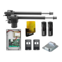
2. General features
Automation for private use sliding gates (max. gate weight 600Kg).
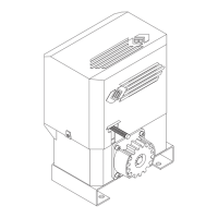
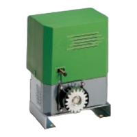
The small and elegant design enbloc RI.6E consists of a painted aluminium unit containing the motor and ir-
reversible reduction unit, realized with high-grade materials. The reduction parts are completely immersed in
oil. The RI.6E has a spring-operated travel-end. A personalized key emergency release enables manual gate
operation in the event of power failure.
3. Foundation slab laying
Secure the foundation slab to the ground with no. 4 steel T pressure inserts to dimensions given in g. 1 (it’s
important the slab is securely fastened to the ground).
N.B.: Go through holes F with a sheath suitable to the actuator feed cables.
4. Rack xing
4.1 Nylon rack (g. 2)
Place the rack at a height of 125 ÷ 126 mm from the base of the foundation slab up to the rack tooth head;
drill and thread M6 the gate approx. in the center line between the rack slots. Now secure the rack and refer
to points 4.3 and 4.4 before proceeding.
4.2 Fe 12x30 mm rack (g. 2)
Weld or screw the spacer pins D onto the gate at 144 ÷ 145 mm above the base of the foundation actuator
slab and maintain the same pitch as the rack drilling. Now secure the rack and refer to points 4.3 and 4.4
before proceeding.
4.3 Keep the pitch of teeth between the two parts of the rack; the joining with another piece of rack would
make it easier to achieve (see g. 2)
4.4 Secure the rack with the screws V making sure, once the actuator has been installed, that between rack
and the drive gear there is always approx. 1 mm clearance (see g. 3); to get this clearance use the slots on
the rack.
5. Actuator positioning and xing (see g. 4)
Remove the case by untightening the screws V. Place the actuator unit so that the gear is centered to the
rack; level it with the grains G and if necessary adjust the clearance between rack and gears (according to
g. 3). Now tighten the screws L.
6. Limit stop ask positioning (see g. 5)
Open manually the gate and leave approximately of 1÷3 cm, depending on gate weight, between gate and
positive mechanical stop A; tighten the limit stop ask S with the grains G to press the limit stop micro. Repeat
the sequence with closing gate.
7. Manual operation
To operate the gate manually, use the release as follows (see g. 6):
- once inserted the personalized key C, turn it anticlockwise and pull the lever L.
- to reset the standard operation running, close the lever L and operate the gate manually, until engage-
ment.
 Loading...