17
Regulating the limit stop cams (fig. 4)
The regulation of the limit stop cams allows:
Cam A
Anticipate or delay the start of the slowing phase in opening (Fig.3- point “B”).
Cam C
Regulate with precision the stopping point in closing (Fig.3 - point “D”).
Note: Before activating the closing limit stop (Fig.4 - D), the cam C starts the slowing phase, activating the
slowing limit stop (Fig.4 - C).
With reference to Fig.4:
• Slacken the cam fixing screw V.
• Bring the opening or closing cam into the desired position.
• Tighten the cam fixing screw V.
If necessary, it is possible to transform a right-hand barrier into a left-hand one. In the control unit,
invert the motor connections and the limit stops SWC 2 (closing limit stops) and SWC 1 (closing
slowing limit stop).
Accessories to request
• Flash-lights kit art. VE.L650
• Springs kit art. VE.KM24
• Fixed support art. VE.AF
• Mobile support art. VE.AM
• Pneumatical skirting art. SC.P35
• Rack art. VE.RAST
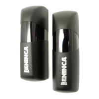
• Photo-electric cells art. SC.P50 / SC.P50E
• Magnetic spiral art. ID.T100
• Battery charger card with battery holder plate art. DA.24CB
CAUTION
The civil liability policy, which covers possible injuries to people or accidents caused by defects in construc-
tion, requires the system to be to existing standard and to use original Benincà accessories.
 Loading...