Do you have a question about the Benning DUSPOL and is the answer not in the manual?
Symbol indicating equipment for working under voltage.
Symbol for a manually actuated push button.
Symbol for alternating current.
Symbol for direct current.
Symbol for direct and alternating current.
Logic for indications occurring when both push buttons are actuated.
Symbol for clockwise phase sequence.
Logic for phase sequence indication at 50/60 Hz.
Symbol showing correct battery polarity alignment.
Signal lamp for optical continuity check.
Buzzer for acoustic continuity check.
Symbol for phase and phase-sequence indication.
Symbol 'R' for phase sequence indication.
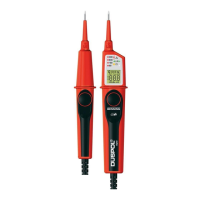
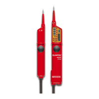
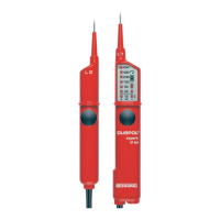
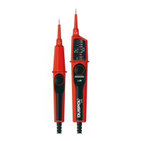
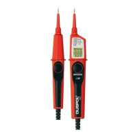
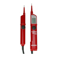
Description of the tester's probes, cable, and display.
Voltage levels indicated by LEDs without push buttons.
Operation with reduced resistance when push buttons are pressed.
Motor vibration aids in estimating voltage levels.
Device prevents overheating during load tests.
High-contrast LEDs indicate voltage levels and polarity.
LC display for phase tests and phase-sequence indication.
Verify correct operation before use by testing functions.
Procedure for testing AC voltages using the tester.
Test for live phase using probe L1; 'R' symbol indicates live phase.
Procedure for testing DC voltages using the tester.
Determine polarity of DC voltage using LED indicators.
Procedure for testing phase sequence in three-phase mains.
Test for electrically conductive connections (0-108 kΩ).
Instructions for replacing the tester's batteries.
Guidelines for environmentally responsible battery disposal.
Specifications including standards, voltage, resistance, and environment.
Cleaning instructions for the voltage tester housing.
Information on proper disposal of the product at end of life.
| Display | LED |
|---|---|
| Frequency Range | 16Hz to 400Hz |
| Continuity Test | Yes |
| Polarity Test | Yes |
| Single-Pole Phase Test | Yes |
| Safety Category | CAT IV 600V |
| Battery Type | 2 x 1.5V AAA |
| Weight | Approx. 200g |
| Safety Standards | EN 61243-3, VDE 0682-401 |


 Loading...