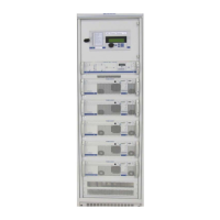
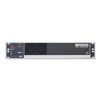
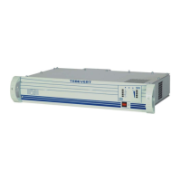
Switch mode, single-phase, sine-wave Inverter
Product line TEBEVERT
August 8, 2005 - DTL 17/21 No. 4219en R2
All connections are carried out at the rear of the inverter. (See Figure 4 and block
diagram / appendix A)
1) Connect the personnel safety ground conductor to the appropriate
marked studs.
• Cable cross section: 10 AWG – 6 AWG, maximum
• Connection via two hole lugs (1/4” x 5/8”) suitable for the cable cross
section
• Nominal range of tightening torque: ( 4,5 – 6 ) Nm, use 10mm socket
wrench.
2) Connect the DC-supply conductor to the CU-bars X1(+) and X1(-)
Attention! Ensure correct polarity
• Cable cross section: 10 AWG – 6 AWG, maximum
• Connection via two hole lugs (1/4” x 5/8”) suitable for the cable cross
section
• Recommended protection device: 25A Fuse or Circuit Breaker
• Nominal range of tightening torque: ( 4,5 – 6 ) Nm, use 10mm socket
wrench.
3) Plug customer load into receptacle X3; X4 (NEMA 5-15 R )
4) Optional - Plug Commercial AC bypass (if required) into the inlet X2
(IEC/EN 60320-1) Benning Pt. No. 220-1000-102, IEC-320-14 line
cord, 7’-6” long.
5) Connect the potential free central alarm to X5;1, 2 or 3 as required,
screw terminals (M2)
• Cable cross section: 28 AWG – 16 AWG
• Max load: 160VAC / 8A
• Max. Fusing, if required: depends on the cross section of the cable
used; see appropriate local codes (e.g. NEC)
• Nominal range of tightening torque: (0,22 – 0,25) Nm
Attention!
Only CU-conductors should be used.
All connecting cables must be provided with appropriate strain
relief. (see appropriate national standards; e.g. NEC )


 To Next Page