INSTALLATION
It is necessary to mount the ECHO siren on an
even wall, free from hollows or excessive
bumps which might jeopadize the proper func-
tioning of the tamper device.
To facilitate system installation, a drill pattern
is included in the package, as are also the
adequate screws for the correct mounting.
There are five holes on the fitting pattern F1,
F2, F3 and F4 corresponding to the fitting
points on the back of the siren, F5 is for the S
bracket (see fig. 4).
Be careful not to over tighten this last screw as
this may damage the tongues A (see fig. 4).
Once the siren is mounted, it is possible to
carry out the connections on the M terminal
board M. The battery should then be posi-
tioned on the battery support MP (fig. 4), and
then connected: the flasher will then start to
function. Fit the inner cover and container and
wait for the flasher to stop (approx. 45 secs).
At this point the siren is enabled and ready for
testing.
PROBLEMS
If the flasher does not function when the bat-
tery is connected, it may indicate that the bat-
tery is low. To check the battery status, close
the cover, wait approximately 45 seconds and
provoke an alarm. If the siren starts, even at
low acoustic level but the flasher does not
function, the battery is low: it can then be re-
charged in several hours by means of the +N
terminal.
If when the battery is connected, the covers
are closed, and the 45 seconds have passed,
the flasher continues flashing, check that both
microswitches are closed properly, and the
adequate tension is present (13.8 V on +N, -A
disconnected) on the alarm terminal board.
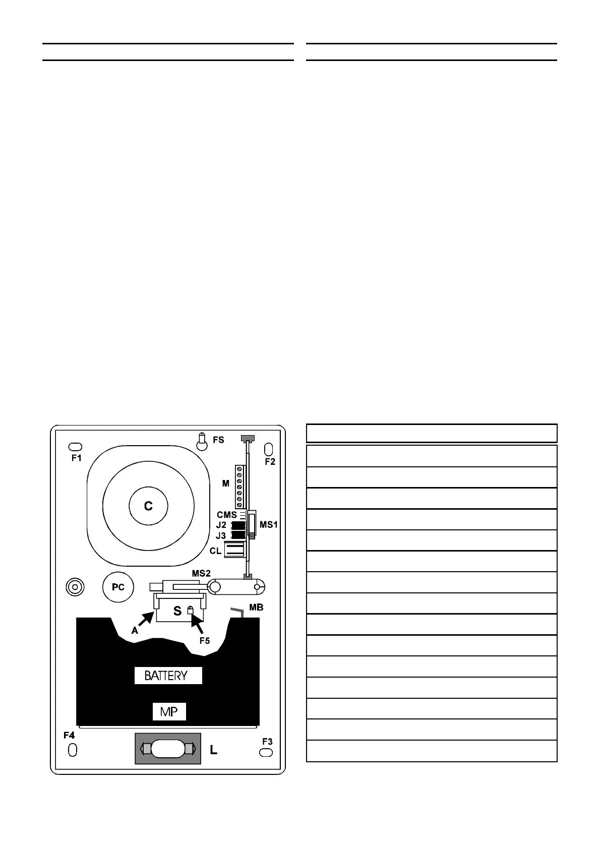
IDENTIFICATION OF THE PARTS
F1-F2-F3-F4 Fixing holes.
F5 Supplementary hole.
FS Braket fixing hole.
PC Cable passage.
L Flashing light.
MP Battery support.
S Microswitch braket.
A Tongues.
C Exponential horn.
MS1-MS2 Antitamper microswitches.
M Terminal board.
CMS MS2 connection.
J2-J3 Jumpers.
CL Flashing light connection.
MB Battery terminal board.
+ The technical specifications of the prod-
uct are subject to change without notice.
Fig. 4 - Identification of the parts.